The proposed LED sound level meter will detect the sound hitting the MIC, and indicate its volume level through an array of LED, connected as a bar graph.
Circuit Description
From the figure below, you can see the Sound Level Meter. Audible tone is detected by MIC1 (an electret microphone element) and is delivered to the input of the first op-amp, U1-a.
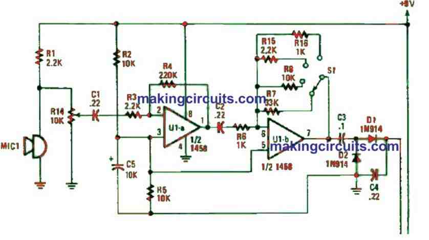
This is half of an LM1458N dual op-amp. R3 and R4 values configure the op-amp’s gain which is equal R4/R3 at 100.
You can achieve this by utilizing the values shown for the resistors. The signal is then channeled to the input of the second op-amp (U1-b), where it is enhanced again by a factor between 1 and 33. This depends on the setting of the range switch, S1.
If the range switch is set in the “A” position, R6 is 1 k and R7 is 33 k. Configuring in this way allows the stage to have a gain of 33. In the “B” position, the gain is 10; and in positions “C” and “D”, the gains are 2.2 and 1, respectively.
Op-amp U1-b’s output is transformed to a changing DC signal by a voltage doubler.
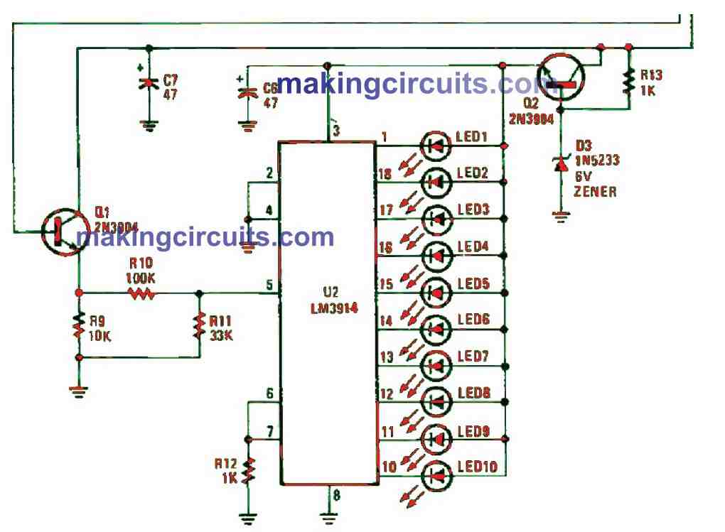
This rectifier circuit is built of components D1, D2, C3 and C4. Transistor Q1 is attached in an emitter-follower circuit to separate the DC signal from the input network of U2 (an LM3914 dot/bor display driver).
Transistor Q2, Zener diode D3, and resistor R13 construct a voltage regulator circuit that lessens the 9-V power supply to a regulated 5 V supply which is used to power U2. The latter is connected to the dot-display configuration.
As the signal voltage supplied to the input of U2 at pin 5 differs, one of ten LEDs will be lit to match with the input voltage level.
At the input’s lowest operating level, U2 generates an output at pin 1 which forces LED1 to light. The highest input level showed to the input of U2 (around 1.2 V) causes LED10 to light up.
Resistors R10 and R11 form a standard voltage-divider network, which brings down Q1’s output-signal voltage to an operating range that pairs the input requirements of U2.
Resistor R12 configures the LED’s drive current. The light output of the LED’s can be enhanced by decreasing the value of R12 or lessened by bringing up the resistor’s value. The lower limit value R12 must not be less than 680 Ω.
While the circuit schematic is not that crucial, tidiness and short connecting leads will make it look more organised as an end-product.
The sound level indicator circuit can be constructed on a perfboard or if you’re handy, it can be done on a PCB.
If you opt for a perfboard, use sockets for the ICs. Assemble the circuit in a small plastic case with MIC1 attached in one end and the LEDs and the range switch placed on the top if you look into using the sound meter frequently.
The simplest way to tune the sound-level meter is using another commercial sound meter.
If that is not possible, you can choose the following way particularly if the circuit will be applied to make relative sound-level comparisons.
Some suppliers offer a number of cheap piezo sounders for which the producers have detailed a dB output-sound level at a secured distance.
How to Calibrate
Calibration of this LED sound level meter is simple – choose a sounder with a specified output dB level (say 100 dB) at a distance of one inch and put the MIC1 about the same distance from the sounder. After that, configure the range-switch S1 until the 5th LED becomes lit. This means the sound range is at 100 dB.
This seamless calibration means we can determine the approximate values of switch position. They are: Position A = 65 dB to 85 dB; position B = 80 dB to 96 dB; position C = 94 dB to 105 dB; and position D = 100 dB to more than 115 dB.
At close range, a jet aircraft produces sound more than 120 dB which is so close to the pain threshold. Similarly, the surrounding noise from a manufacturing plant is around 65 dB to more than 80 dB.
A standard conversation between two persons measured from a distance of 1 foot is almost 75 dB to 80 dB. To check the circuit, just place the microphone about one foot away from you and speak casually.
At the same, adjust R14 so that LED5 is lit on the “A” range. This simple sound-meter, although not a high-end unit, is capable of measuring common noises pretty well.
Parts List

Leave a Reply