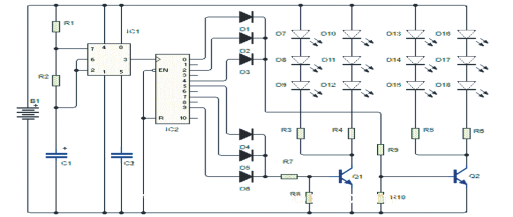
When we power this police strobe light circuit it produces the familiar strobe light effect seen in police cars.
How We Achieve the Effect
To create this effect we use two sets of lights, specifically LEDs that activate alternately. When one set is on its corresponding LED flashes three times. Then the other set activates and follows the same pattern. This process continues indefinitely.
This flashing effect is similar to strobe lights often used in dance halls.
Circuit Functionality
Our circuit utilizes a 555 timer in conjunction with a 4017B decade counter. By adjusting the resistor and capacitor values connected to the timer we can change the clock speed. The default values allow the circuit to function effectively.
The 4017B outputs a high signal level sequentially across its outputs. We connect outputs 0, 2, 4, 5, 7, and 9 for our setup.
This connection enables the diodes to flash as each group of LEDs is activated.
It's important to note that outputs 1, 3, 6, and 8 are not connected. These outputs determine the duration for which the display LEDs remain off.
We connect the first group of LEDs to outputs 0, 2, and 4, while the second group connects to outputs 5, 7, and 9.

Parts List
| Component | Description |
|---|---|
| IC1 | 555 timer |
| IC2 | 4017B decade counter |
| Q1, Q2 | 2N2222 or 8050 transistor |
| D1 to D6 | 1N4007 diodes |
| D7 to D18 | RED 5mm LEDs |
| R1 | 1K resistor |
| R2 | 22K resistor |
| R3 to R10 | 470 ohm resistors |
| C1 | 2.2uF/25V capacitor |
| C2 | 0.01uF ceramic disc capacitor |
| Power Supply | 12V DC supply or battery (B +) |
Leave a Reply