• Skip to main content
  • Skip to primary sidebar

Making Easy Circuits

Learn and build electronic circuits

You are here: Home / Battery Chargers / Prevent Battery Self-Discharge using this Circuit

Prevent Battery Self-Discharge using this Circuit

Last Updated on November 5, 2020 by Admin Leave a Comment

The simple circuit presented in this article safeguards a lead acid battery from self-discharging, especially when the battery is not being used or charged for long periods of time.

The unit not only protects the battery from self-discharging, it keeps the battery fully charged and in a topped up condition, thus maintaining an overall good health for the battery in all conditions.

This circuit is very useful for maintaining lead-acid batteries that are lying dormant for a long time but still work.

The circuit charges the battery and lets it discharge slowly using the internal resistance of the battery itself and the circuit.

Once a state of charge or the SoC is met, the charger is switched on again. The battery will be charged again and the whole process repeats continuously.

How the Circuit Works

Reffering to the schematic below, the unit is built using a Schmitt trigger T1/T2 Zener, the circuit also consists of Zener diode D7 that sets the state of charge where the charger is turned off. Resistor R2 supplies the needed hysteresis.

self discharge protector compressed

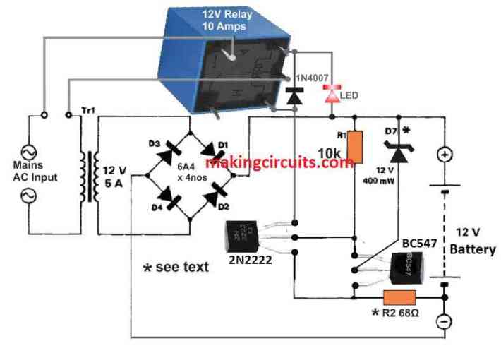
Since the mains is disconnected and there is no battery attached to the respective terminals, examine if the relay switches on and off using voltages from a regulated power supply.

How to Set Up

To set up this self-discharge battery protector circuit, adjust the voltage so that 13.6 V and 12.5 V are placed across the battery terminals. You can tune the ‘on’ threshold by attaching a 1N4148 (cathode to the positive line) in series with D7. The ‘off’ threshold value can be adjusted by modifying the R2 value. For instance, you may replace this resistor with a 100-ohm preset.

There is also a possibility of replacing the mains transformer and bridge rectifier with a battery charger.

With this setup, the rest of the circuit can be assembled into the charger.

But remember, it is impossible to connect a completely discharged battery (below 10V) to the circuit because the relay will not be energized.

Instead, you should charge such a battery to more than 10 V. Another workaround is to place a switch in parallel with the relay contact and turn off the mains using the switch.

Using Two Batteries

You could also maintain and protect self-discharge for two 12 V batteries on a condition that the secondary voltage of the mains transformer, the Zener voltage of D7, the hysteresis and coil voltage are doubled.

Besides, you must ensure the batteries are connected in series across the terminals. We recommend using fuse F1 to safeguard the components against a short-circuit.

You can also do the same for protecting the transformer primary circuit using a 1 A fuse. Since the whole activity revolves around the battery, a smoothing capacitor is not required by the circuit.

You'll also like:

  • 1.  Automatic Lead Acid Battery Charger Circuit Using IC 555
  • 2.  NiCd Battery Charger Circuit using Transistors
  • 3.  Self Regulating Battery Charger Circuit
  • 4.  Convert any SMPS Adapter into a Solar Charger
  • 5.  Incubator Heater Backup Circuit with Charger
  • 6.  Make this Cheapest MPPT like Solar Charger Circuit

About Admin

Hey friends, Thanks a bunch for stopping by this site! I am an engineer with a Bachelor of Engineering in Electronics and Telecommunication. One of my passions is gathering information from all sorts of electronics books and tutorials. I then take that information and compile it into a language that is super easy to understand. My goal is to make those complex electronics circuit concepts and technical terms much more accessible for all the new and budding electronics engineers out there. I can also design customized circuit diagrams as required by the users.
If you have any questions related to this field, please do not hesitate to drop a comment! I am always here and ready to help you out with any queries you might have. I cannot wait to hear from you!

Reader Interactions

Leave a Reply Cancel reply

Your email address will not be published. Required fields are marked *

Primary Sidebar

Categories

  • 3 Phase (4)
  • 8051 Microcontroller (1)
  • Arduino (11)
  • Audio and Amplifier (102)
  • Automation (8)
  • Battery Chargers (64)
  • Bicycle Projects (4)
  • Car and Motorcycle Projects (39)
  • Datasheets (10)
  • DIY Projects (5)
  • Electrical (15)
  • Free Energy (6)
  • Games Projects (2)
  • High Voltage (14)
  • Hobby Projects (30)
  • Household Circuits (2)
  • IC 555 Circuits (4)
  • Ignition Circuits (2)
  • Indicators (50)
  • Infrared (6)
  • Inverter Circuits (29)
  • Lights and Lamps (97)
  • Medical (8)
  • Meter and Tester Circuits (38)
  • Motor Driver (17)
  • New Circuits (56)
  • Oscillators (30)
  • Pets and Pests (5)
  • Power supply (81)
  • Protection Circuits (25)
  • PWM (8)
  • Remote Control (20)
  • Security and Alarm Circuit (48)
  • Sensors and Detectors (66)
  • Signal Processor (23)
  • Solar Controller Circuits (61)
  • SSR (3)
  • Temperature Controller (20)
  • Timer (25)
  • Transformerless (7)
  • Transmitters (12)
  • Tutorials (45)
  • UPS (2)
  • Voltage Regulators (57)
  • Water Sensor and Controller (29)
  • Home
  • Privacy Policy
  • Contact
  • Disclaimer
  • Copyright

© 2025 · Making Easy Circuits