This project discusses in detail about the PWM lamp dimmer. It will use IC NE555. Earlier the dimmers built on linear regulators was not efficient compared to the current one. For instance, if the old dimmers can achieve efficiency of 50% the new one is quite efficient to achieve 90%. Moreover, while the less power goes for waste turning into heat, the PWN dimmers’ switching need a small heat sink. This actually reduces the size and thus further positive impact on its weight. Overall, lamp dimmers based on PWM is more efficient when compared to the previous ones.
The following diagram provides an elaborate sketch of 12V PWM lamp dimmer:
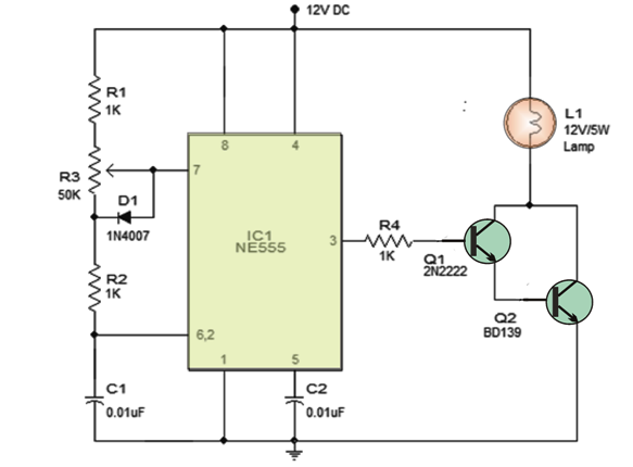
Referring to the circuit design it is clear that IC timer NE555, which is the core of the system is wired into the circuit in the form astable multi-vibrator. Here, R1, R2, POT R3 resistors and C1 capacitors are the main components for timing. To adjust the duty cycle of the IC, POT R3 is used. If the duty cycle is higher then the lamp gets brighter or vice versa. When the astable multi-vibrator is on a charging cycle, the D1 Diode avoids the lower section of POT R3. This mechanism is simply to maintain constant output frequency no matter whatever is the condition of the duty cycle. The Q1 and Q2 transistor builds a darlington driver stage for a lamp of 12V. The R4 resistor on the other hand restricts base current of Q1 transistor.
Explaining variable duty cycle astable multi-vibrator
For ease of understanding, the timing of the astable multi-vibrator is explained in the diagram below [Fig 1.1]:

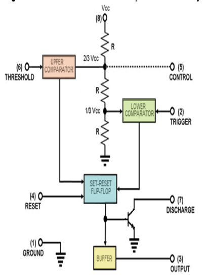
Referring to the figure, as you see the upper and lower parts of POT R3 is signified as Rx, Ry. Now when the output of the astable multi-vibrator is set to high, the C1 Capacitor then moves through R1, Rx, R2. On the other hand, Ry which signifies the lower part of POT R3 is negligible, since D1 Diode avoids it. When the capacitors voltage is 2/3 Vcc, the upper comparator simply flips the output. This makes internal flip-flop to manage toggling the output. This procedure results lowdown of astable multi-vibrator. To sum up, an astable multi-vibrator remains in high state till the charge available in C1 is equal to 2/3 Vcc. The equation states thus:
Ton = 0.67 (R1 + Rx + R2) C1.
Now as the internal flip-flop is all set, the capacitor then discharges via R2, Ry, straight to the discharge pin. When C1 capacitor’s voltage is 1/3 Vcc, the lower comparator again flips the output, which evidently enables the internal flip-flop manage toggle its output. This, according to the equation would be:
Toff = 0.67 (R2 + Ry) C1.
Following is a diagram of NE555 to enable better explanation of the system:
Constant Frequency irrespective of the situation of POT3
The total resistance always remains same no matter where POT3 knob is placed. If there is a decrease in Rx (upper-side) then Ry also gets increased with the same amount. The similar situation is applicable to Ton and Toff.
Following is a calculation to make it easier [as per Figure 1.2]:
Ton = 0.67(R1+Rx+R2)C1
Toff= 0.67(R2+Ry)C1
Output of the waveform “T”, total time:
T = Ton + Toff
So, T = 0.67(R1+Rx+R2+R2+Ry)C1
T= 0.67(R1+2R2+Rx+Ry)C1
While Rx + Ry = R3
So, T = 0.67(R1+2R2+R3)C1
And Frequency F = 1/(0.67(R1+2R2+R3)C1
It has become therefore imperative that frequency is only dependent on C1, R1 and R2 and moreover R3. There is connection on the knob position.
Leave a Reply