• Skip to main content
  • Skip to primary sidebar

Making Easy Circuits

Learn and build electronic circuits

You are here: Home / Signal Processor / How to Build a RF Signal Jammer Circuit

How to Build a RF Signal Jammer Circuit

Last Updated on February 17, 2018 by Admin Leave a Comment

The article represents an uncomplicated homemade RF signal jammer circuit that anyone can use for jamming any RF signal within a radial selection of 10 meters.


RF2Bsignal2Bjammer2Bcircuit
A basic appearing RF signal jammer circuit can be watched in the above diagram, that could be effective at jamming different kinds RF signal within the choice of 5 to 10 meters.
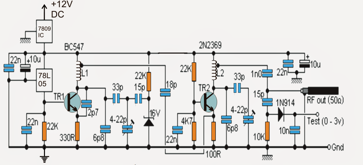
The circuit can be accomplished suitable with any expected frequency to be jammed by merely making use of various sets of L1/L2 and by amending the 22pF trimmers appropriately. The frequency that is certainly jammed making use of this circuit could possibly be well within the range of 50 MHz to 1Ghz, in spite of this rendering it suitable for frequencies above 500 MHz could easily get much complex and parameters much important on account of the fact that higher frequencies need shorter interconnections and may consist of other steadiness problems.
The existing design can be employed for jamming FM radio stations located in the within 40 meters radial distance or even higher. On the other hand the unit may be utilized as an effective 1km range audio transmitter by providing a MIC input across the pont mentioned "Test".
The circuity of the suggested RF signal jammer is essentially composed of two different phases: The one consisting T1 and the relevant parts form the RF oscillator stage while the other stage comprise of T2 and the complementing parts for amplifying and transmitting the low voltage oscillations from T1 into the air.
The above solid RF carrier signals transmitted by T2 might be accordingly modulated with any external frequency for example an audio or speech by supplying the signal across the terminal suggested "Test".
The circuit is definitely sturdy and does not need to falter with different input supply voltages as a result of the existence of the 78L05 voltage regulator at the base of T1 which clamps the base of T1 with a continuing biasing current ensuring the oscillations produced by the T1 stage remains very sturdy and continuous.
The above characteristic is completely enhanced by the T2 stage which welcomes the oscillations from the T1 stage and amplifies and converts the signals with much higher current to ensure that the signals have the ability to travel across larger radial distances in the air.
On the other hand to be able to make use of an optimal transmission of the signals, 50 OHM impedance antenna must be employed with the output of the circuit.
This may be any normal aluminum dipole yagi antenna. An easy flexible wire measuring about a meter would certainly also do but would certainly reduce the transmission strength by about 60 % producing the unit much ineffective with regards to the transmission range is concerned.
For producing the RF jammer appropriate for other frequencies, the coil L1 and L2 ought to be shortened concerning their number of turns and/or also the diameter...this will require some testing until the appropriate frequency is identified.
The adjoining trimmers may additionally tweaked for obtaining an optimal result from the jammer circuit or until a good jamming is accomplished by means of the circuit.
A good quality, well designed PCB is strictly suitable for starting the RF jammer circuit
The submit illustrate a fairly easy homemade RF signal jammer circuit that can be employed for jamming any RF signal within a radial choice of 10 meters.
A basic seeming RF signal jammer circuit can be visible in the above diagram, which can be efficient at jamming a wide range RF signal within the selection of 5 to 10 meters.
The circuit can be achieved suitable with any desirable frequency to be jammed by merely employing several sets of L1/L2 and by revising the 22pF trimmers suitably. The frequency which is usually jammed implementing this circuit may very well be well of about 50 MHz to 1Ghz, on the other hand making it very suitable for frequencies above 500 MHz could possibly get much complex and parameters much important as a result of the fact that higher frequencies prefer shorter interconnections and may comprise of other constancy difficulties.
The current design should be considered for jamming FM radio stations situated the within 40 meters radial distance or even higher. Additionally the unit can certainly be utilized as an impressive 1km range audio transmitter by providing a MIC input across the pont mentioned "Test".
The circuity of the recommended RF signal jammer is simply created of two specific levels: The one composing of T1 and the related parts form the RF oscillator stage while the other stage containing T2 and the complementing parts for amplifying and transmitting the low voltage oscillations from T1 into the air.
The above powerful RF carrier signals transmitted by T2 could be effectively modulated with any external frequency for instance an audio or speech by supplying the signal across the terminal suggested "Test".
The circuit is extremely dependable and is not going to falter with various input supply voltages on account of the occurrence of the 78L05 voltage regulator at the base of T1 which clamps the base of T1 with a persisting biasing current being sure that the oscillations developed by the T1 stage continues very solid and dependable.
The above function is absolutely accompanied by the T2 stage which allows the oscillations from the T1 stage and amplifies and modifies the signals with much higher current in order that the signals can easily travel across larger radial distances in the air.
In spite of this in an effort to carry out an optimal transmission of the signals, 50 OHM impedance antenna must be employed with the output of the circuit.
This might be any regular aluminum dipole yagi antenna. An easy flexible wire measuring about a meter would likely also do but would probably reduce the transmission strength by about 60 % providing the unit much incompetent as long as the transmission range is concerned.
To create the RF jammer appropriate for other frequencies, the coil L1 and L2 will have to be shortened with regards to their number of turns and/or also the diameter...this will desire some trials until the correct frequency is established.
The adjoining trimmers might also tweaked for finding an optimal reply from the jammer circuit or until an awesome jamming is obtained by way of the circuit.
A good quality, well designed PCB is strictly advisable for producing the RF jammer circuit

You'll also like:

  • 1.  Sine wave Generator Circuit using Wein Bridge Oscillator
  • 2.  Simple Tachometer Circuit
  • 3.  Simple Sawtooth Generator Circuit
  • 4.  Dog Barking Sound Simulator Circuit
  • 5.  5 Band Graphic Equalizer Circuit
  • 6.  Simple Voltage Controlled Oscillator using IC 555

About Admin

Hey friends, Thanks a bunch for stopping by this site! I am an engineer with a Bachelor of Engineering in Electronics and Telecommunication. One of my passions is gathering information from all sorts of electronics books and tutorials. I then take that information and compile it into a language that is super easy to understand. My goal is to make those complex electronics circuit concepts and technical terms much more accessible for all the new and budding electronics engineers out there. I can also design customized circuit diagrams as required by the users.
If you have any questions related to this field, please do not hesitate to drop a comment! I am always here and ready to help you out with any queries you might have. I cannot wait to hear from you!

Reader Interactions

Leave a Reply Cancel reply

Your email address will not be published. Required fields are marked *

How to Make a Powerful RF Signal Jammer Circuit

Last Updated on November 29, 2014 by Admin Leave a Comment

The post describes a simple homemade RF signal jammer circuit that can be used for jamming any RF signal within a radial range of 10 meters. The idea was requested by one of the interested readers of this blog.

Technical Specifications

I am not a large business interest, but am in need of a circuit which would not only help me, but eventually be welcomed by just about everyone now alive.

I am in need of a circuit which will jam RFsignals. I realize jammers are illegal when they disrupt cellphone communication and commercial enterprise. I am only looking to jam (1.) remotely controlled harassment devices and (2.) spyware within the confines of my property. Jamming range limited to around a 25' x 25' area.

There is a growing community of victims of electronic harassment. We all experience an invasion of our personal lives/finances and private conversations, and are sometimes physically stalked and attacked.

Due to the nature of electronic harassment, it will take time for justice and protection to catch up and solve the problem. As for electronics, some circuits to control the misuse of flux & solder are long overdue in the marketplace.

Up until now, most of the interest has been placed on projects of invasion and abuse, such as those contained on many different website

I am not overly skilled in electronics, and only come to it in self defense. I am self taught and can follow a schematic and complete a project, and am slowly gaining understanding of the underlying theory.

Please advise regarding your interest to help, and your financial requirements. I look forward to hearing from you.

Circuit Diagram

RF2Bsignal2Bjammer2Bcircuit

Parts List

  • All resistors are 1/4 watt 5% CFR
  • 22 K = 3
  • 330 Ohms = 1
  • 4.7 K = 1
  • 100 Ohm = 1
  • 10 K = 1
  • Capacitors are all Ceramic Disc, unless specified
  • 22 nF = 4
  • 2.7 pF = 1
  • 6.8 pF = 2
  • 33 pF = 2
  • 15 pF = 2
  • 18 pF = 1
  • 10 nF = 1
  • 1 nF = 1
  • 10 uF / 25 V Electrolytic = 2
  • Trimmers 33 pF = 2
  • Semiconductors
  • Zener Diode 16 V 1 watt = 1
  • 1N914 Diode = 1
  • TR1 = BC547
  • TR2 = 2N2369
  • IC7809 = 1
  • IC 78L05 = 1
  • Inductors = See Text
  • Antenna = Telescopic antenna

Introduction

A simple looking RF signal jammer circuit can be seen in the above diagram, which may be capable of jamming all sorts RF signal within the range of 5 to 10 meters.

The circuit can be made suitable with any desired frequency to be jammed by merely using different sets of L1/L2 and by tweaking the 22pF trimmers accordingly.

The frequency that could be jammed using this circuit could be well in the range of 50 MHz to 1Ghz, however making it compatible with frequencies above 500 MHz could get much complex and parameters much critical owing to the fact that higher frequencies require shorter interconnections and may involve other stability issues.

The present design can be used for jamming FM radio stations situated in the within 40 meters radial distance or even higher.

The circuity of the proposed RF signal jammer is basically made of two distinct stages:

RF Circuit Stages

The one comprising T1 and the associated parts form the RF oscillator stage while the other stage consisting of T2 and the complementing parts for amplifying and transmitting the low voltage oscillations from T1 into the air.

The above strong RF carrier signals transmitted by T2 may be appropriately modulated with any external frequency such as an audio or speech by feeding the signal across the terminal indicated "Test".

The circuit is highly stable and doesn't falter with varying input supply voltages due to the presence of the 78L05 voltage regulator at the base of T1 which clamps the base of T1 with a constant biasing current making sure that the oscillations created by the T1 stage stays very stable and consistent.

The above feature is perfectly complemented by the T2 stage which accepts the oscillations from the T1 stage and amplifies and transforms the signals with much higher current so that the signals are able to travel across larger radial distances in the air.

However in order to implement an optimal transmission of the signals, 50 OHM impedance antenna must be used with the output of the circuit.

This could be any ordinary aluminum dipole yagi antenna. A simple flexible wire measuring about a meter would also do but would reduce the transmission strength by about 60 % making the unit much inefficient as far as the transmission range is concerned.

How to Peak the Resonance

The performance of the RF jammer could be highly improved by adjusting the presets to produce peak resonance. This can be done with the following points:

  1. Connect a 0 - 10V DC voltmeter across the point "test" and the ground line.
  2. Adjust the right side 22p trimmer such that the meter reads around a maximum of 3V on the meter.
  3. This might disturb the initial frequency of the system that you might have set for the jamming purpose.
  4. So go back to the left side 22p trimmer and fine tune it again to set the desired frequency back into place.

Your peak resonance for the circuit is set now, and you can expect maximum efficiency from it.

RF Jammer Coil Specifications

For making the RF jammer compatible with other frequencies, the coil L1 and L2 must be shortened in terms of their number of turns and/or also the diameter...this will need some experimentation until the right frequency is determined.

The adjoining trimmers may also tweaked for getting an optimal response from the jammer circuit or until a perfect jamming is achieved through the circuit.

A good quality, well designed PCB is strictly recommended for constructing the RF jammer circuit

For jamming standard FM broadcasts within a range of 50 meters, L1 and L2 may be built as indicated in the following images:

all 1

PCB Etched RF Coil

The above image shows the construction L2 using a 7 turn, 1mm super enameled copper wire with a diameter of approximately 5 to 6mm (internal)....see how the tap is extracted from the relevant end of the coil.

bug9 all 1

The following image shows how L1 can be designed by etching the tracks on the PCB itself or the same could be built using pieces of diode leads as explained in this FM wireless MIC circuit

PCB Designs

Jammer PCB track layout
jammer PCB component layout

You'll also like:

  • 1.  How to Build a Vibrating Cell Phone Remote Control Circuit
  • 2.  How to Make a Remote Controlled Pulley Hoist Mechanism Circuit Part-1
  • 3.  433 MHz Encoder and Decoder Pinouts Explained
  • 4.  IR Remote Controlled Door Lock Circuit
  • 5.  GSM based Irrigation Circuit using Cellphone missed Calls and Arduino
  • 6.  Wireless Lamp using an RF Disturbance Circuit

About Admin

Hey friends, Thanks a bunch for stopping by this site! I am an engineer with a Bachelor of Engineering in Electronics and Telecommunication. One of my passions is gathering information from all sorts of electronics books and tutorials. I then take that information and compile it into a language that is super easy to understand. My goal is to make those complex electronics circuit concepts and technical terms much more accessible for all the new and budding electronics engineers out there. I can also design customized circuit diagrams as required by the users.
If you have any questions related to this field, please do not hesitate to drop a comment! I am always here and ready to help you out with any queries you might have. I cannot wait to hear from you!

Reader Interactions

Leave a Reply Cancel reply

Your email address will not be published. Required fields are marked *

Primary Sidebar

Categories

  • 3 Phase (4)
  • 8051 Microcontroller (1)
  • Arduino (11)
  • Audio and Amplifier (102)
  • Automation (8)
  • Battery Chargers (64)
  • Bicycle Projects (4)
  • Car and Motorcycle Projects (39)
  • Datasheets (10)
  • DIY Projects (5)
  • Electrical (15)
  • Free Energy (6)
  • Games Projects (2)
  • High Voltage (14)
  • Hobby Projects (30)
  • Household Circuits (2)
  • IC 555 Circuits (4)
  • Ignition Circuits (2)
  • Indicators (50)
  • Infrared (6)
  • Inverter Circuits (29)
  • Lights and Lamps (97)
  • Medical (8)
  • Meter and Tester Circuits (38)
  • Motor Driver (17)
  • New Circuits (56)
  • Oscillators (30)
  • Pets and Pests (5)
  • Power supply (81)
  • Protection Circuits (25)
  • PWM (8)
  • Remote Control (20)
  • Security and Alarm Circuit (48)
  • Sensors and Detectors (66)
  • Signal Processor (23)
  • Solar Controller Circuits (61)
  • SSR (3)
  • Temperature Controller (20)
  • Timer (25)
  • Transformerless (7)
  • Transmitters (12)
  • Tutorials (45)
  • UPS (2)
  • Voltage Regulators (57)
  • Water Sensor and Controller (29)
  • Home
  • Privacy Policy
  • Contact
  • Disclaimer
  • Copyright

© 2025 · Making Easy Circuits