• Skip to main content
  • Skip to primary sidebar

Making Easy Circuits

Learn and build electronic circuits

You are here: Home / Motor Driver / Servo Motor Driver and Tester Circuit

Servo Motor Driver and Tester Circuit

Last Updated on December 4, 2020 by Admin Leave a Comment

The servomotor driver and tester unit might excite two types of electronic enthusiasts namely model vehicle owners and robotic system builders.

As shown in the diagram, the circuit equips a standard 555 or 7555 timer chip. This IC is configured so that the circuit can drive two or more servomotors simultaneously.

servo motor tester compressed

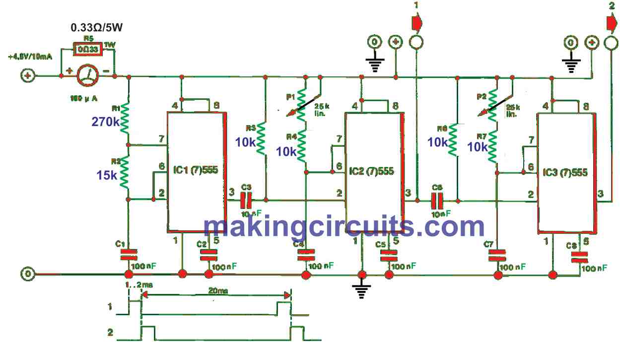
You may also notice the second and third stages of the circuit are exact. IC1 acts as an unstable multivibrator whose output pulse period time is set using the formula:

T = 0.639(R1 + R2)C

The displayed values for the associated timing sections will eventually deliver a pulse period time of around 20 ms at pin 3 of IC1.

The square wave’s rising edge activates IC2 which is monostable. The output pulse width of IC2 can be regulated with P1.

The series connection of P1 and R4 warrants a huge pulse width range for almost all servo motors which usually need around 1 or 2 ms of activation pulse widths.

The second servo control stage is the same as the configuration of IC2 and 8 other activated stages of the 555 timers.

To cater to the motor’s angular and linear positions, each of the servo control potentiometers is recommended to be fitted with a standard scale to view its relative indication.

How to Test Servo-Motor Current

To monitor the total current consumption of the connected servomotors, an ammeter is connected in series with the positive supply line. Moreover, the ammeter detects when one or more servos gets stuck.

The servo motor test circuit itself consumes negligible current, compared to the total current consumption with motor as identified on the meter.

The value is about 3 mA for each 555-type timer in the row. In case 7555-type timers are utilized, the current drawn is much lower than 3 mA. Therefore, it may be viable to convert the tester into a portable, NiCd battery-powered device.

You'll also like:

  • 1.  Automatic Sliding Door Circuit
  • 2.  How to Build a Pedal Speed Controller Circuit for Electric Vehicles Part-1
  • 3.  How To Make a Fan Speed Controller for Heatsink
  • 4.  How Brushless DC (BLDC) Motors Work
  • 5.  Simple DC Motor Speed Controller Circuit
  • 6.  High Current Motor Speed Controller Driver Circuit

About Admin

Hey friends, Thanks a bunch for stopping by this site! I am an engineer with a Bachelor of Engineering in Electronics and Telecommunication. One of my passions is gathering information from all sorts of electronics books and tutorials. I then take that information and compile it into a language that is super easy to understand. My goal is to make those complex electronics circuit concepts and technical terms much more accessible for all the new and budding electronics engineers out there. I can also design customized circuit diagrams as required by the users.
If you have any questions related to this field, please do not hesitate to drop a comment! I am always here and ready to help you out with any queries you might have. I cannot wait to hear from you!

Reader Interactions

Leave a Reply Cancel reply

Your email address will not be published. Required fields are marked *

Primary Sidebar

Categories

  • 3 Phase (4)
  • 8051 Microcontroller (1)
  • Arduino (11)
  • Audio and Amplifier (102)
  • Automation (8)
  • Battery Chargers (64)
  • Bicycle Projects (4)
  • Car and Motorcycle Projects (39)
  • Datasheets (10)
  • DIY Projects (5)
  • Electrical (15)
  • Free Energy (6)
  • Games Projects (2)
  • High Voltage (14)
  • Hobby Projects (30)
  • Household Circuits (2)
  • IC 555 Circuits (5)
  • Ignition Circuits (2)
  • Indicators (50)
  • Infrared (6)
  • Inverter Circuits (29)
  • Lights and Lamps (97)
  • Medical (8)
  • Meter and Tester Circuits (38)
  • Motor Driver (17)
  • New Circuits (56)
  • Oscillators (30)
  • Pets and Pests (5)
  • Power supply (80)
  • Protection Circuits (25)
  • PWM (9)
  • Remote Control (20)
  • Security and Alarm Circuit (48)
  • Sensors and Detectors (66)
  • Signal Processor (23)
  • Solar Controller Circuits (62)
  • SSR (3)
  • Temperature Controller (20)
  • Timer (25)
  • Transformerless (7)
  • Transmitters (12)
  • Tutorials (45)
  • UPS (2)
  • Voltage Regulators (57)
  • Water Sensor and Controller (29)
  • Home
  • Privacy Policy
  • Contact
  • Disclaimer
  • Copyright

© 2025 · Making Easy Circuits