One of the widely used electronic devices are servos or also known as servo motors. These components are compact, almost weightless, cost-friendly and incredibly easy to use. In model building, servos are connected straight to an RF receiver unit.
They usually occupy three connections namely the positive supply (+5 V), ground (GND) and control (Pulse) lead. The pulse lead delivers a control signal to actuate the servo arm.
Furthermore, the signal on this lead is subjected to pulse-width modulation (PWM) and delivered by the receiver. Positive pulses with 1 ms of length cause the servo arm to actuate completely from one end of its travel. If 2 ms pulses are used, the arm moves fully in the reverse direction.
Pulse widths (PWMs) between these limits actuate the arm to a middle-range position proportional to the pulse-width. A 1.5-ms pulse-width centers the arm and the pulse reiteration rate are close to 20 ms or about 50 Hz. However, this is not so important.
If you suspect that the model is not functioning as it should, there may be an issue with the remote-control transmitter, receiver or a servo motor.
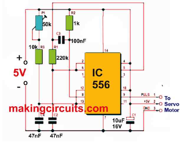
This flexible servo motor tester circuit permits you to rapidly examine the servo and remove any non-factors from your diagnostic steps. Further, this pulse generator design as depicted in Figure 1 the is most common type known to electronic enthusiasts.
How the Circuit Works
A dual-timer chip type NE556 makes up the pulse generator. The output pulse-width is governed by the position of a potentiometer. The grouping of resistor R1 and capacitor C2 in timer 1 of NE556 generates the repetition rate of the pulse.
This timer output signal at pin 5 occupies a symmetrical mark space ration. The negative-going edge of the output signal is utilized through C3 to activate the second timer. This action generates a positive-going output pulse at pin 9. The value of capacitor C4 and the combined resistance of R3 and P1 describe the width of the pulse. Finally, control of the pulse-width is given by pot P1.
Test Results
When testing, we found this servo tester circuit with the component values described here generated a pulse-width in the range of 0.5 to 2.6 ms. This interval is more than adequate to cover the typical pulse-width range utilized by these kinds of servos.
Because of that, P1 must not be turned completely to either end of its travel. Else, the linked servo will move past its planned end position and crash into the mechanical stoppers, most likely damaging the servo. Before the circuit is switched on, you must make sure the control know P1 is in about the middle position. The pulse iteration rate was identified to be 18 ms.
Most of the servos function with a supply voltage in the range of 4.8 to 6 V. In this setup, we have used the range 5 to 6 V which can be delivered by two pairs of AA primary cells or rechargeable ones.
Leave a Reply