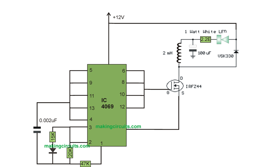
Here is an illustration of this efficiently operating a Simple 1 Watt LED Driver Circuit from a 12 volt battery power implementing a buck converter. The LED may perhaps plainly be tied to a series resistor to achieve the expected current, but then the efficiency could well be barely 25% because the resistor could possibly reduce 9 volts although the LED simply demands 3. The driver part works by using a CMOS hex inverter (CD4069) in which a couple of of the inverters structure an oscillator with 31% duty cycle at approximately 11.5 Khz, or 66us off time, as well as 21uS ON-time for the MOSFET switch.
The Simple 1 Watt LED Driver Circuit buck converter presents approximately 90% efficiency. The concept it to try to determine a running current by using the inductor, diode and load, at the same time the switch fills up the missing load energy on a single cycle. The duty cycle of the switch will likely be the output voltage broken down by the input voltage, or roughly 3/12 (25%) for this reason. It happens to be basically somewhat higher considering that you have minimal (2.2 ohm) resistor in series with the LED that decreases about 0.5 volt, so the overall load is around 3.7 volts as well as the duty cycle is around 31%. The circuit can even be inured to charge AA batteries from a 12 volt source with modification to the duty-cycle.
The smallest inductor significance was ironed out from E = L * di/dt and a LED current of 250mA. The lowest significance will be where the current drops to 0 in the course of the turn off period, or 66uS. The maximum inductor current may well in that case be 2 times the average or 500mA while the inductor is going to charge from 0 to 500mA in 21uS. As a result, di/dt is 0.5 /.000021 = 23810 amps per second.
The rest of the 4 inverters are utilized in parallel to produce supplementary drive current to the gate of the MOSFET. The duty-cycle could possibly be tweaked with a choice between the 15K or 20K resistors.
The inductor voltage (E) is going to be 12 subtracted the load voltage 3.7 or 8.3 volts as well as the least inductor significance L might be 8.3 / 23810 = 0.35 mH. The specific rates considered a good choice ought to be a tad bit greater to refrain from the current weakening to zero as well as to refrain from big peak currents and conceivable saturation.
The illustration at this point works by using a anticipated 2 mH inductor as a result the alternation in current refers to 100mA and the maximum current is cheaper at about 300mA.
The current waveform of this Simple 1 Watt LED Driver Circuit is usually as demonstrated in the LTspice picture below. Take note of the current ramps from approximately 50mA below the typical current to approximately 50mA above the standard or approximately 100mA absolute change. The 15 ohm resistor in the LTspice image corresponds to the LED as well as a 2.2 ohm resistor. The MOSFET is symbolized by the SW (switch) component, in addition to the drive circuit by the V3 symbol.
Leave a Reply