• Skip to main content
  • Skip to primary sidebar

Making Easy Circuits

Learn and build electronic circuits

You are here: Home / Audio and Amplifier / Simple 100 Watt Amplifier Circuit using 2N3055 Transistors

Simple 100 Watt Amplifier Circuit using 2N3055 Transistors

Last Updated on November 16, 2024 by Admin 32 Comments

Here we learn how to make a very simple 100 watt amplifier circuit using a 2N3055 transistors and a few other passive components.

Simply by incorporating just four transistors in the quasi-complementary configuration this 2N3055 simple power amplifier circuit can deliver a good 100 watts of power over an attached 4 ohms loud speaker, and the entire design can be built at a really low cost (to be precise it would cost you only 1/2$ per transistor).

Simple 100 Watt Amplifier Circuit using 2N3055 Transistors

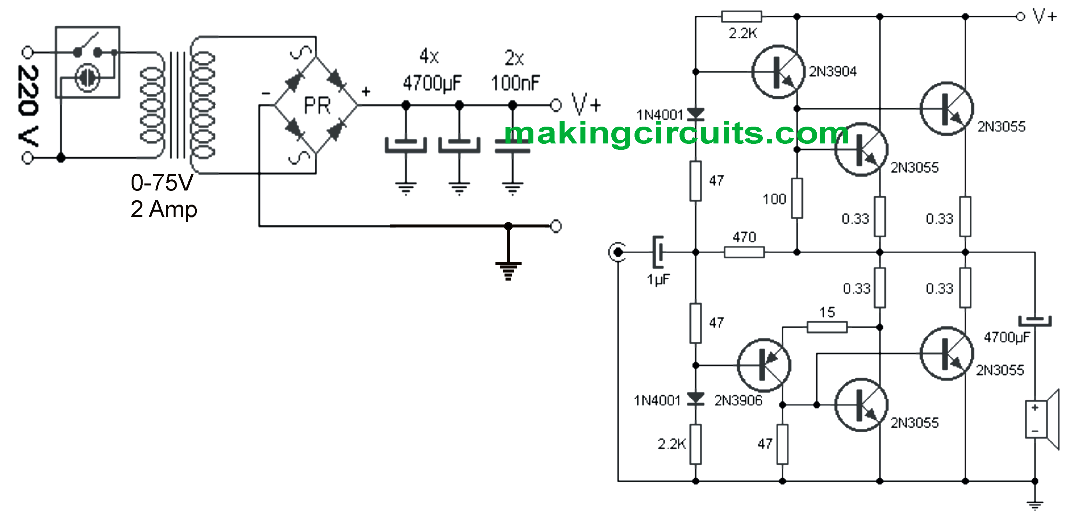
As exhibited in the above diagram you won't find no costly or obsolete hard to find components in this amplifier circuit, except the power supply transformer and possibly the 4 ohm loud speaker.

The input stage is created by configuring a couple of current drivers transistor stages responsible for triggering the pairs of power BJTs positioned at the output stage.

The 2N3055 power stage at the output should be mounted on large heat sinks to ensure that this crucial stage is able to dissipate adequately and function with optimal efficiency.

The a power supply of 80V, it becomes necessary to put a series capacitor in between the output stage and the speaker in order to block the DC supply from entering the speaker and allowing only the amplified 100 watt music power.

For a mono 100 watt amplifier the power supply could be rated at 1.5A , for stereo this needs to be doubled at 3 amps, and in case a quadraphonic amplifier is required then make sure to use transformer rated to handle a minimum of 6 amp.

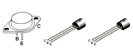
The following diagram shows the pinout details of the various transistors used in this simple 100 watt amplifier circuit using 2N3055 transistors

2N3055 pinouts

You'll also like:

  • 1.  Buzzer Circuit Using a Transistor and Piezo Element
  • 2.  Precision Guitar Tuner Circuit
  • 3.  Bass Treble Tone Control Circuits – 3 Designs Discussed
  • 4.  Simplest Homemade Electric Guitar
  • 5.  Very Low Frequency (VLF) Converter Circuit
  • 6.  Design your Own Notch Filter Circuits

About Admin

Hey friends, Thanks a bunch for stopping by this site! I am an engineer with a Bachelor of Engineering in Electronics and Telecommunication. One of my passions is gathering information from all sorts of electronics books and tutorials. I then take that information and compile it into a language that is super easy to understand. My goal is to make those complex electronics circuit concepts and technical terms much more accessible for all the new and budding electronics engineers out there. I can also design customized circuit diagrams as required by the users.
If you have any questions related to this field, please do not hesitate to drop a comment! I am always here and ready to help you out with any queries you might have. I cannot wait to hear from you!

Reader Interactions

Comments

  1. cobus H says

    April 21, 2022 at 2:00 am

    I build this amplifier but get no audio out, did check all my connections over again. Please tell me the lowest voltage that this amplifier will start on? I tried 32v just to make sure everything is up and running but no luck. Also the speaker wire, for under 80v must the 4700mfd capacitor ommitted or not?
    thank you so much
    Cobus

    Reply
    • admin says

      April 22, 2022 at 4:46 pm

      The lowest voltage can be 12V. The 4700uF capacitor is compulsory, it cannot be omitted.

      Reply
  2. Dave says

    December 23, 2020 at 2:32 am

    2N3055 can’t handle 80 volts – 70 volts tops. Vce rating is 60v but you could squeeze a little more by running a 50v ac secondary into a bridge and smoothing to give around 71 volts off load. Any more and these things would pop regularly. Their main utility is that they could handle 15 amps.

    Reply
    • admin says

      January 2, 2021 at 12:37 pm

      You are right, in that case you can replace them with TIP35

      Reply
  3. jayanath says

    October 10, 2020 at 6:49 pm

    dear sir do you have any amplifier circuit for public address loudspeakers (Horns) ?

    Reply
    • admin says

      October 11, 2020 at 1:21 pm

      yes I may be having it, will check and let you know….

      Reply
  4. Chukwuma onyekwuluje says

    July 16, 2020 at 9:03 pm

    Pls how do make simple power amp using two 2n3055,one capacitor and one resistor

    Reply
  5. jayanath says

    June 23, 2020 at 5:59 pm

    what is the wattage of 0.33 ohm resistors please? is it 5w?

    Reply
    • admin says

      July 7, 2020 at 7:23 pm

      they are all 1 watt rated

      Reply
  6. Shong geu says

    June 18, 2020 at 11:26 am

    Bonjour,
    Votre schéma amplificateur est-il HI-FI?

    Cordialement.

    Reply
    • admin says

      June 19, 2020 at 7:21 pm

      Bonjour,
      Oui c’est Hi Fi

      Reply
  7. David says

    February 28, 2020 at 9:34 pm

    I made this circuit (almost identical) 50 years ago with only one set of 3055’s (yes I am 72) It is very robust I still use it every day…..Use good quality caps.

    Reply
  8. Marc says

    November 4, 2019 at 6:09 am

    could you tell me the wattage of resistance 0.33 thank you, god bless you

    Reply
    • admin says

      November 8, 2019 at 1:57 pm

      you can use 3 watt resistors

      Reply
  9. angelo corsaro says

    October 26, 2019 at 1:38 pm

    To have 100 W ( RMS ? ) how many mV should be the audio input ?
    The Arrangement seem to have a gain of (just) 4 dB . So i suppose the input should be at least ( also depending of speker impedance ) 12 Vp/p . Right ?

    Reply
    • admin says

      November 1, 2019 at 4:59 pm

      yes that’s correct!

      Reply
    • Geert Zijlstra says

      February 27, 2022 at 12:01 am

      this amplifier has no dc gain! i simulated it

      Reply
  10. KrisM says

    October 16, 2019 at 5:24 pm

    Hello, should this not have PNP and NPN in the output buffer too?

    I did not think about it at first so just went with NPN and got no output.

    Reply
    • admin says

      November 1, 2019 at 4:53 pm

      Are you getting output with PNP? According to me the original diagram is correct.

      Reply
  11. Uttam khatua says

    January 3, 2019 at 10:49 pm

    Bord me (-)vold kaha dunga

    Reply
    • admin says

      January 12, 2019 at 4:13 pm

      speaker ground line par!

      Reply
  12. cedrick says

    February 24, 2018 at 4:21 pm

    Can it still deliver 100 watts by using a 8ohm instrumental speaker

    Reply
  13. dix says

    January 6, 2018 at 1:13 pm

    Hi is this really work?… what transistor can be replaced to 3904/3906.. its because not available to my country TIA .. reply will be appreciated thanks!

    Reply
    • admin says

      January 7, 2018 at 3:22 pm

      thanks dix you can replace them with 2N2222 and 2N2907

      Reply
      • Phil Pearce says

        January 11, 2023 at 2:13 am

        The 3906 and 3904 transistor bases are incorrectly wired to the input circuit. They should be connected to the cathode side of their respective diodes not the anodes.

        Reply
  14. L. Khomei says

    December 7, 2017 at 7:12 pm

    Kindly make clear the rated voltage of 4700 uf capacitors

    Reply
    • admin says

      December 7, 2017 at 8:47 pm

      it should be twice of the transformer voltage rating

      Reply
  15. Christopher Chapman says

    September 21, 2017 at 5:18 pm

    In the above 2N3055 100 watt simple power amplifier; should the 1N4001 diodes be mounted on the heatsink with the power transistors?

    Reply
    • admin says

      September 22, 2017 at 11:08 am

      please use 6A4 diodes instead, 1N4001 may burn due to over current

      Reply
      • admin says

        September 22, 2017 at 11:10 am

        I am sorry, I thought you were referring to the bridge diodes…the 1N4001 diodes will not require any heatsink

        Reply
        • Christopher Chapman says

          September 27, 2017 at 6:59 am

          That will work for me; thanks!!!!! 🙂

          Reply
          • admin says

            September 27, 2017 at 8:18 am

            You are welcome!!

Leave a Reply Cancel reply

Your email address will not be published. Required fields are marked *

Primary Sidebar

Categories

  • 3 Phase (4)
  • 8051 Microcontroller (1)
  • Arduino (11)
  • Audio and Amplifier (102)
  • Automation (8)
  • Battery Chargers (64)
  • Bicycle Projects (4)
  • Car and Motorcycle Projects (39)
  • Datasheets (10)
  • DIY Projects (5)
  • Electrical (15)
  • Free Energy (6)
  • Games Projects (2)
  • High Voltage (14)
  • Hobby Projects (30)
  • Household Circuits (2)
  • IC 555 Circuits (5)
  • Ignition Circuits (2)
  • Indicators (50)
  • Infrared (6)
  • Inverter Circuits (29)
  • Lights and Lamps (97)
  • Medical (8)
  • Meter and Tester Circuits (38)
  • Motor Driver (17)
  • New Circuits (56)
  • Oscillators (30)
  • Pets and Pests (5)
  • Power supply (80)
  • Protection Circuits (25)
  • PWM (9)
  • Remote Control (20)
  • Security and Alarm Circuit (48)
  • Sensors and Detectors (66)
  • Signal Processor (23)
  • Solar Controller Circuits (62)
  • SSR (3)
  • Temperature Controller (20)
  • Timer (25)
  • Transformerless (7)
  • Transmitters (12)
  • Tutorials (45)
  • UPS (2)
  • Voltage Regulators (57)
  • Water Sensor and Controller (29)
  • Home
  • Privacy Policy
  • Contact
  • Disclaimer
  • Copyright

© 2025 · Making Easy Circuits