This 250 watt power amplifier circuit to deliver 250 watts of massive music power into a 4 ohm speaker with utmost clarity.
Use complementary transistors to achieve the desired power. It is powered by a 45V + 45V source and consumes 5 amps. All transistors, except BC556C must be mounted on the heatsink, which must be one of the sides of the cabinet. The diodes marked A, B and C are 1N4001 and must also be mounted on the heat sink but with thermal grease. The input must be standard 1Vpp line.

How the Amplifier Produces 250 watts of Power
At first it seems that the amplifier may not be able to deliver the proposed 250 watt of music power into a 4 ohm speaker.
However, the amplifier is capable of rated power output without any issue, provided the output transistors are all mounted on large finned type of heatsinks.
The basic operation can be understood from the following points:
The music input is filtered by the RC filter network connected at the base of the pre-amplifier stage using BC556 pair of transistor.
The RC network blocks all high frequency interference and allows only the music input between 10 Hz and 20 kHz.
The BC556 pair actually also works as a mirror amplifier, and makes sure that the subsequent stage in the amplifier works with a constant current, and therefore with higher stability.
The power amplifier stage can e seen directly configured with the mirro amplifier stage through a pair of 270uF coupling capacitors.
The power output stage is built using symmetrical NPN PNP transistors arrays, power optimum power output and high efficiency.
The NPN power transistor is directly configured with the BC556 pre-amplifier while the lower PNP power transistor stgae is attached through an inverting stage using BC139 transistor stage. This is essential since the BC556 being a PNP itself cannot directly bias the output PNP stage.
The power supply does not have to be stabilized but if well filtered. We recommend following the following scheme:
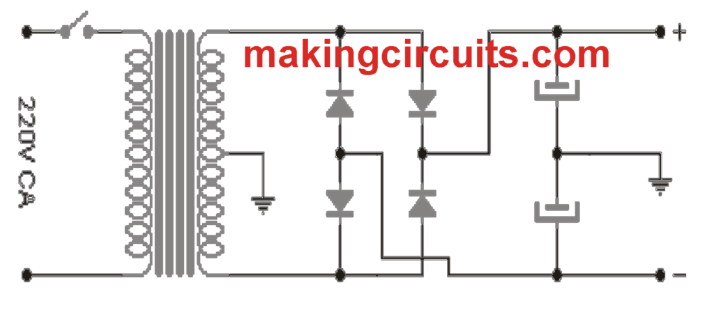
In this case the transformer has a secondary with central socket of 32-0-32 (or 64V with central socket). For a mono configuration it must have a current of 5A, for stereo 10A. The diodes must be at least 100V by 6A for mono and 100V 12A for stereo. Capacitors must be 4700µF 63V each. Do not use higher voltages since that would affect the capacitor's work curve (it would not filter optimally).
has the system been tested in practice or is it just a theoretical design?
* emitter resistors much too large – maybe they were supposed to be 0.47Ω each?
* 10Ω resistor in series with the speaker – maybe someone gave the speaker resistance in this way? but I think it’s a mistake, because such resistance is too big;
* transistors TIP140 and TIP145 are 60V – so the power supply can be up to +-30V;
* to conduct 10A through such a transistor, a base current of at most 20mA is enough, but at 6A, 1.5mA is typically enough – it seems that for typical examples of power transistors, the use of BD139/BD140 is unnecessary (and it requires higher voltage on diodes A, B, C ) – mistake?
* no regulation of quiescent current and input balancing;
* without BD139/BD140: assuming the peak current of the power transistors of about 6A and the voltage amplitude of 20V, you can count on the power of 120W with a 1.6Ω speaker; you could get a bit more, amplitude from 24V and power 144W with a 2Ω speaker, but the emitter resistors would have to be a bit smaller; no chance at 250W;
* with BD139/BD140: here you can have a peak current of 10A, but the voltage amplitude will probably not exceed 20V, the speaker would have to be 1Ω – theoretical power of 200W;
* emitter resistors are used to improve thermal stability – first of all, they protect against uneven current distribution causing overheating of one transistor, and against an increase in the quiescent current of power transistors (temperature increase => U_BE decreases => current increases =>…); too small will not be effective, too large will unnecessarily reduce the power of the amplifier.
Thank you for the detailed analysis of the circuit, it is much appreciated.
However, I am not sure whether the design is tested or not because it was contributed by an external author….
send to me schematic circuits diagram of amplifier single power using transistor
https://makingcircuits.com/blog/1-watt-amplifier-circuit/