• Skip to main content
  • Skip to primary sidebar

Making Easy Circuits

Learn and build electronic circuits

You are here: Home / New Circuits / Simple Bent Wire Game Circuit

Simple Bent Wire Game Circuit

Last Updated on March 30, 2020 by Admin Leave a Comment

The bent wire game is quite a popular game. There is a bent wire in an electrical circuit and a ring has to be passed over the wire without touching it. Both the wire and the ring are placed as such that whenever they come into contact a bell starts ringing or a LED glows up.

It is easy to make an electrical arrangement in the circuit so that instead of ringing momentarily, the bell rings or the LED glows for a second or two. This shows the connection between the wire and the ring even if it is done very briefly.

bent wire game circuit

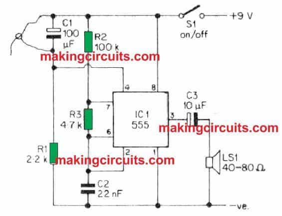
How the Circuit Works

The circuit of the game has a 555 astable to let a loud speaker work and create an audible tone. Moreover, to control the oscillator, voltage is applied to pin 4 of the 555. The timing components of R1 and C1 provide the voltage to pin 4 of IC1.

C1 and R1 are connected in such a way that they are placed across the supply rails. C1 is uncharged when the switch is on and so pin 4 develops a positive voltage. However, C1 develops enough voltage very soon so that pin 4 of IC1 cannot support the oscillation anymore. This makes the audible sound go off after a second once the circuit is disconnected.

The bent wire and C1 are in parallel connection. So in case of any short circuit C1 will be completely discharged, leading to the production of audible signal again. The loud sound continues to work until C1 is charged fully again. This shows that the ring and the wire has come to contact.

Construction

The best way to construct a bent wire game is by placing the loudspeaker and switch on the front panel of a plastic case. The bent wire is placed at the top of the panel by drilling holes and creating smaller holes and then passing the wire through the holes.

The ends of the wire is flattened and glued in correct position using an epoxy adhesive. If no epoxy adhesive is available, a small copper wire can be used but the wire then should not be insulated. However, at two ends, there must be some insulation to keep the ring at rest without creating a circuit.

In case general copper wire is not used, a 16swg can be a good alternative. The insulation at both the ends should be made by tapes. Another interesting way is to use a crocodile clip for this.

The ring and the lead can be made by the general PVC-insulated wire. One end of the wire being threaded and inserted in the holes and the other being 50mm of insulation removed from it.

Now, a loop of bare wire is made around the bent wire. The loops of the bare wire are made as such that it is of optimum length. The loop is then bent carefully into a bent and neat circle. Trial and error mode is used to determine the best size of the loop which then determines the toughness of the game.
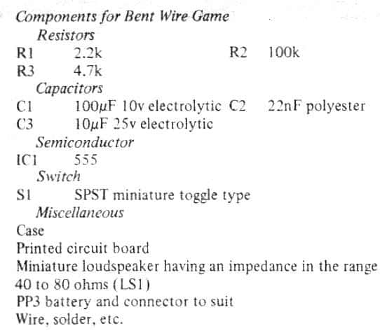
Parts List

parts list

You'll also like:

  • 1.  Light Dimmer Circuit Diagram 1000 Watts
  • 2.  How to Make Logic Inverter, Buffer Gates using BJTs
  • 3.  Simplest Transistor Running Light Circuit for Christmas Lighting Decoration
  • 4.  PWM Amplifier Circuit
  • 5.  How to Build a LM317 as a Variable Voltage Regulator and Variable Current Regulator
  • 6.  How to Build a Thunder Lightning Detector Circuit

About Admin

Hey friends, Thanks a bunch for stopping by this site! I am an engineer with a Bachelor of Engineering in Electronics and Telecommunication. One of my passions is gathering information from all sorts of electronics books and tutorials. I then take that information and compile it into a language that is super easy to understand. My goal is to make those complex electronics circuit concepts and technical terms much more accessible for all the new and budding electronics engineers out there. I can also design customized circuit diagrams as required by the users.
If you have any questions related to this field, please do not hesitate to drop a comment! I am always here and ready to help you out with any queries you might have. I cannot wait to hear from you!

Reader Interactions

Leave a Reply Cancel reply

Your email address will not be published. Required fields are marked *

Primary Sidebar

Categories

  • 3 Phase (4)
  • 8051 Microcontroller (1)
  • Arduino (11)
  • Audio and Amplifier (102)
  • Automation (8)
  • Battery Chargers (64)
  • Bicycle Projects (4)
  • Car and Motorcycle Projects (39)
  • Datasheets (10)
  • DIY Projects (5)
  • Electrical (15)
  • Free Energy (6)
  • Games Projects (2)
  • High Voltage (14)
  • Hobby Projects (30)
  • Household Circuits (2)
  • IC 555 Circuits (5)
  • Ignition Circuits (2)
  • Indicators (50)
  • Infrared (6)
  • Inverter Circuits (29)
  • Lights and Lamps (97)
  • Medical (8)
  • Meter and Tester Circuits (38)
  • Motor Driver (17)
  • New Circuits (56)
  • Oscillators (30)
  • Pets and Pests (5)
  • Power supply (80)
  • Protection Circuits (25)
  • PWM (9)
  • Remote Control (20)
  • Security and Alarm Circuit (48)
  • Sensors and Detectors (66)
  • Signal Processor (23)
  • Solar Controller Circuits (62)
  • SSR (3)
  • Temperature Controller (20)
  • Timer (25)
  • Transformerless (7)
  • Transmitters (12)
  • Tutorials (45)
  • UPS (2)
  • Voltage Regulators (57)
  • Water Sensor and Controller (29)
  • Home
  • Privacy Policy
  • Contact
  • Disclaimer
  • Copyright

© 2025 · Making Easy Circuits