• Skip to main content
  • Skip to primary sidebar

Making Easy Circuits

Learn and build electronic circuits

You are here: Home / Protection Circuits / Simple Code Lock Circuit

Simple Code Lock Circuit

Last Updated on May 14, 2020 by Admin Leave a Comment

This simple code lock circuit can be used to lock doors by pressing a 3 button keypad.

As the simple code lock circuit consists of extremely few components it is also very cheap to build, the code is a 3-Step with no digits it may be repeated, for eg. 123 or 473 are OK, but not 112 or 767th This is the simple version of the circuit can be easily found in the code by simply try after some time.

How the Circuit Works

This circuit I had in my mind for quite some time in the past, just threw it together this weekend.

The assorted-resistance value may seem a little strange I just selected whatever the next-best resistors I had in my junk box.

The values are therefore only indicative and may be chosen as per individual comforts.

With these values, you have to type in the code pretty quickly if you do not want to press all 3 buttons simultaneously.

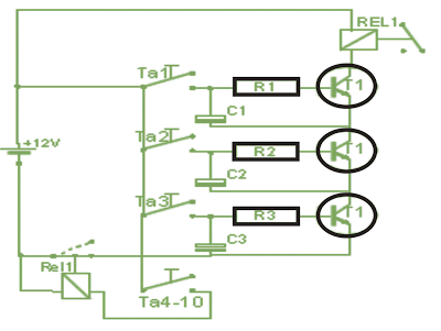
The simple code lock circuit is assembled as per the plan shown below and may be the easiest over a piece of prototype board.

The switches are not soldered to pads, the shown are only for 3 selected out of the 10 keys.

Therefore you solder only the capacitors, resistors, transistors, and the relay, the places where the switches are required could be just ways you can put solder pins.

The 10-button keypad is supplied on the same pole with + voltage, which include the three contacts with the numbers they want to use as the code to be connected to the solder pins. going from bottom to top, ie. In the present diagram the Code is 321

The remaining contacts are soldered to each other and connected to the relay No.2, which locks the circuit.

If you are having difficuty understanding, it's going from the keyboard 5 wires away (3x code button + 1x every other button + 1x positive voltage)

This is necessary because otherwise all the switches could be pressed simultaneously, and thus the code would be triggered.

simple code switch circuit

You'll also like:

  • 1.  Simple Mains Voltage Stabilizer Circuit
  • 2.  What is the Use of MOSFET Body Diode
  • 3.  Mains Surge Protector Circuit [Computer Power Strip]
  • 4.  How Decoupling in Logic Circuits Work
  • 5.  Mains 220V/120V Short Circuit Breaker Protector
  • 6.  Gas Sensor Circuit

About Admin

Hey friends, Thanks a bunch for stopping by this site! I am an engineer with a Bachelor of Engineering in Electronics and Telecommunication. One of my passions is gathering information from all sorts of electronics books and tutorials. I then take that information and compile it into a language that is super easy to understand. My goal is to make those complex electronics circuit concepts and technical terms much more accessible for all the new and budding electronics engineers out there. I can also design customized circuit diagrams as required by the users.
If you have any questions related to this field, please do not hesitate to drop a comment! I am always here and ready to help you out with any queries you might have. I cannot wait to hear from you!

Reader Interactions

Leave a Reply Cancel reply

Your email address will not be published. Required fields are marked *

Primary Sidebar

Categories

  • 3 Phase (4)
  • 8051 Microcontroller (1)
  • Arduino (11)
  • Audio and Amplifier (102)
  • Automation (8)
  • Battery Chargers (64)
  • Bicycle Projects (4)
  • Car and Motorcycle Projects (39)
  • Datasheets (10)
  • DIY Projects (5)
  • Electrical (15)
  • Free Energy (6)
  • Games Projects (2)
  • High Voltage (14)
  • Hobby Projects (30)
  • Household Circuits (2)
  • IC 555 Circuits (5)
  • Ignition Circuits (2)
  • Indicators (50)
  • Infrared (6)
  • Inverter Circuits (29)
  • Lights and Lamps (97)
  • Medical (8)
  • Meter and Tester Circuits (38)
  • Motor Driver (17)
  • New Circuits (56)
  • Oscillators (30)
  • Pets and Pests (5)
  • Power supply (80)
  • Protection Circuits (25)
  • PWM (9)
  • Remote Control (20)
  • Security and Alarm Circuit (48)
  • Sensors and Detectors (66)
  • Signal Processor (23)
  • Solar Controller Circuits (62)
  • SSR (3)
  • Temperature Controller (20)
  • Timer (25)
  • Transformerless (7)
  • Transmitters (12)
  • Tutorials (45)
  • UPS (2)
  • Voltage Regulators (57)
  • Water Sensor and Controller (29)
  • Home
  • Privacy Policy
  • Contact
  • Disclaimer
  • Copyright

© 2025 · Making Easy Circuits