The final circuit we will see deploys the ceramic sensor that is readily available.
If you have experienced the difficult to detect the source of a low noise knock or ping in a mechanical device, then construct this circuit which works as a knock detector and locator.
The applications are various including in a vehicle, robotic equipment or even in printing presses.
How the Circuit Works

The schematic diagram shown in Figure 1 above is for the detector circuit where capacitor C1 is utilized as a sensor. The sensor’s output signal is amplified a few hundred times by op-amps U1-a and U1-b. then, potentiometer R8 functions as the sensitivity control.
The boosted output of U1-b is regulated by the voltage-doubler circuit made from C3, C2, D1 and D2. The doubler circuit’s DC output is supplied to U1-c’s input, which is set as a voltage follower. Additionally, U1-c’s output is supplied to a 1 mA meter. We are using potentiometer R9 to set the maximum current level for the meter.
The discharge time for C2 is configured using R6’s value. If the value is too much, the meter will need more time to fully recharge and return to a zero value between the input signals. When the value is too small, the meter’s needle will not have enough time to reach its peak reading before C2’s voltage is discharged.
A 1 MΩ resistor is more than enough a value for R6. However, if there are recurrent knocks, you can elevate the value to 10 MΩ and the meter will hold the reading for a short interval to trace the noise to its cause without difficulty.
How to Build
You can build this knock detector circuit straightforwardly on a perfboard and encapsulate it within a small plastic case. Just make sure you have sufficient space for the meter, battery, R8, R9 and the on/off toggle switch, S1. It is advisable to use a socket for the IC. Also, make it a practice to keep the component leads short and tidy wiring.
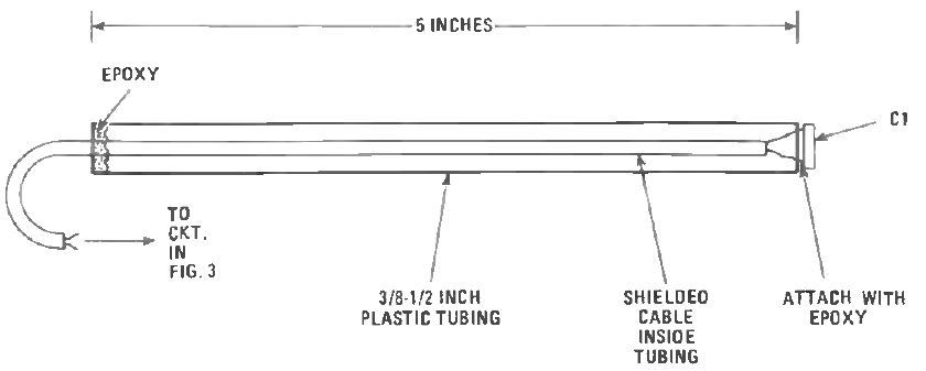
Based on the circuit in Figure above, you can easily replicate the pick-up probe. However, we recommend checking C1 if it can be laid flat against the item being checked to make sure it has maximum sensitivity to the shockwave produced by the knocking sound. You must use at minimum, a three-foot long shielded cable when connecting the probe to the circuit so that it can reach complicated areas.
How to Use
Using the knock detector equipment is fairly simple. First, you must set the gain control for maximum gain and hit the sensor end of the probe on a tough object. After that, you must adjust R9 for a complete scale meter reading.
Arrange the probe flat against the object you wish to check and observe the meter’s reading every time the knock happens.
You have to move the probe in the direction that triggers the meter’s reading to increase. There is a possibility that you might need to tone down the gain setting when approaching the source of the knock using the probes.
Leave a Reply