• Skip to main content
  • Skip to primary sidebar

Making Easy Circuits

Learn and build electronic circuits

You are here: Home / Meter and Tester Circuits / Simple LC Meter Circuit for measuring Inductance and Capacitance at Home

Simple LC Meter Circuit for measuring Inductance and Capacitance at Home

Last Updated on March 14, 2020 by Admin Leave a Comment

An LC meter or Indictance/Capacitance meter is multipurpose measuring device which is ued for identifying unknown inductor and capacitor value quickly.

An LC meter is without any doubt essential to anybody associated with electronic circuits.

LC meter circuit

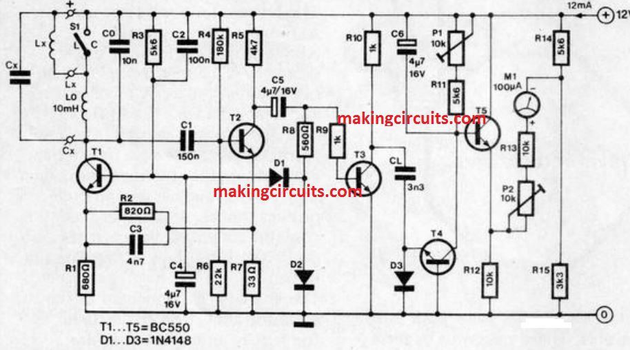
Explained circuit takes the unknown inductance, La, or capacitance, CO, within a 2 transistor oscillator circuit, in which the output voltage is held constant between 30 and 40 mV through a regulator.

If, in the oscillator circuit, Ca is attached in parallel with capacitor Co. or La in series with inductor L0, the frequency of the circuit decreases. This diminution is assessed by a frequency -to -voltage converter, T3/T4. The resultant output voltage of emitter follower T5 is utilized to stimulate meter M1.

Meter M1 is hooked up on the diagonals of a bridge circuit, in order that it shows zero when Ca or La is non existent. The meter is fixed to full-scale reading f.s.d.1 through P2 in case either La = Lo or Ca = Co is introduced into the oscillator circuit.

The threshold of frquency determining capacitor CL in the frequency-to-voltage converter is balanced out by P1.

It is as a result essential to switch with a new 10 k preset for every single measuring range, and anytime this is carried out the f.s.d. must be fixed freshly with P2.

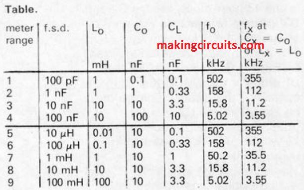
The magnitudes supplied in the circuit for Lo and Co are legitimate for a f.s.d. of 10 nF or 10 m1-1. A highest number of 9 testing ranges could be made available from a 4 way, 9 position rotary switch.

The magnitudes of L., Co CL, and the corresponding frequency, without having Lx or C and at full-scale deflection, are listed in the table. The precision of the readings, provided cautious calibration, is approximately 3 %.

Table

Markings of the range is close to sufficient equal for all ranges, however is 'extended' by a element of about 3 for lower measurements.

This needs, of course, an appropriate correction. Calibrating the scale may be carried Out with a table compiled with the formula ni = nm(1-fr)/(1-fc), where

  • ni = number of scale divisions indicated
  • nm = number of scales divisions at FSD
  • fr = relative frequency
  • fc = lowest relative frequency

Total current consumption amounts to about 12 mA at 20,

You'll also like:

  • 1.  Plant Physiology Analyzer Circuit
  • 2.  Audio Frequency Meter Circuit
  • 3.  Adjustable Continuity Tester Circuit
  • 4.  Millivoltmeter Circuit
  • 5.  FET Voltmeter Circuit
  • 6.  Temperature Meter Circuit using RTD

About Admin

Hey friends, Thanks a bunch for stopping by this site! I am an engineer with a Bachelor of Engineering in Electronics and Telecommunication. One of my passions is gathering information from all sorts of electronics books and tutorials. I then take that information and compile it into a language that is super easy to understand. My goal is to make those complex electronics circuit concepts and technical terms much more accessible for all the new and budding electronics engineers out there. I can also design customized circuit diagrams as required by the users.
If you have any questions related to this field, please do not hesitate to drop a comment! I am always here and ready to help you out with any queries you might have. I cannot wait to hear from you!

Reader Interactions

Leave a Reply Cancel reply

Your email address will not be published. Required fields are marked *

Primary Sidebar

Categories

  • 3 Phase (4)
  • 8051 Microcontroller (1)
  • Arduino (11)
  • Audio and Amplifier (102)
  • Automation (8)
  • Battery Chargers (64)
  • Bicycle Projects (4)
  • Car and Motorcycle Projects (39)
  • Datasheets (10)
  • DIY Projects (5)
  • Electrical (15)
  • Free Energy (6)
  • Games Projects (2)
  • High Voltage (14)
  • Hobby Projects (30)
  • Household Circuits (2)
  • IC 555 Circuits (4)
  • Ignition Circuits (2)
  • Indicators (50)
  • Infrared (6)
  • Inverter Circuits (29)
  • Lights and Lamps (97)
  • Medical (8)
  • Meter and Tester Circuits (38)
  • Motor Driver (17)
  • New Circuits (56)
  • Oscillators (30)
  • Pets and Pests (5)
  • Power supply (81)
  • Protection Circuits (25)
  • PWM (8)
  • Remote Control (20)
  • Security and Alarm Circuit (48)
  • Sensors and Detectors (66)
  • Signal Processor (23)
  • Solar Controller Circuits (61)
  • SSR (3)
  • Temperature Controller (20)
  • Timer (25)
  • Transformerless (7)
  • Transmitters (12)
  • Tutorials (45)
  • UPS (2)
  • Voltage Regulators (57)
  • Water Sensor and Controller (29)
  • Home
  • Privacy Policy
  • Contact
  • Disclaimer
  • Copyright

© 2025 · Making Easy Circuits