• Skip to main content
  • Skip to primary sidebar

Making Easy Circuits

Learn and build electronic circuits

You are here: Home / Audio and Amplifier / Simple Preamplifier Circuit

Simple Preamplifier Circuit

Last Updated on November 16, 2024 by Admin 1 Comment

The circuit discussed is created to work like an universal preamplifier, by adjusting the value of one element, R1, you are able to look after the entire range of inputs explained above.

fig 70

Input signals are combined to the base of Q1 through the isolating capacitor C1 R1 suppresses the input impedance to the right value to match the specific input signal.

R2 and R3 bias Q1 which can be utilized in the most popular emitter mode. Large local AC and DC feedback is presented through R5 which describes the gain of the stage at 20dB.

To overcome noise an MPS6515 is employed at this point controlled with a low collector current, 50uA.

The amplifier's output stage is the darlington pair Q2 and Q3, output signals being extracted from around R7, R8.

R1 needs to be dependant upon experiment but are generally at first identified simply by using a 470R preset in the R1 placement and modifying this for the best possible audio quality by ear.

Single Chip Preamplifier Circuit

The single chip preamplifier circuit presented uses the four Norton op amps comprised during an LM3900 to generate a superior quality stereo preamp, suitable for standared preamplifier application.

fig1 38

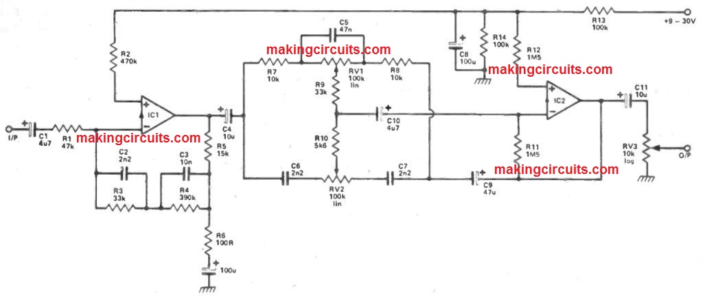
IC1 is utilized within the inverting mode. Signals through the cartridge usually are fed through the obstructing capacitor and R1 to the inverting input.

R1 describes the input impedance and offers the correct controlling for the input signal. R5 and R6 explain the midband gain of the stage whilst the network R3, R4, C2 and C3 supply the needed RIAA equalisation.

From here the equalised signal is fed to a common Baxendall tone control network constructed about IC2.

This needs minor comment while it needs to be observed that individual volume controls are used for every channel.

Not only does this minimizes crosstalk amongst channels but in addition works more affordable in that only a couple of single gang potentiometers are employed.

Efficiency of this single chip preamplifier circuit is decent with general distortion lower than 0.1% and a S / N ratio of -67db without a load, ref 500 mV out.

You'll also like:

  • 1.  Anti-Acoustic Feedback Circuit For Microphone/Amplifier Systems
  • 2.  Stereo Hi-Fi Headphone Amplifier Circuit
  • 3.  Simplest Homemade Electric Guitar
  • 4.  Simple Telephone Amplifier Circuit
  • 5.  Simple Treble Booster Circuit
  • 6.  Headphone Loudness Controller Circuit

About Admin

Hey friends, Thanks a bunch for stopping by this site! I am an engineer with a Bachelor of Engineering in Electronics and Telecommunication. One of my passions is gathering information from all sorts of electronics books and tutorials. I then take that information and compile it into a language that is super easy to understand. My goal is to make those complex electronics circuit concepts and technical terms much more accessible for all the new and budding electronics engineers out there. I can also design customized circuit diagrams as required by the users.
If you have any questions related to this field, please do not hesitate to drop a comment! I am always here and ready to help you out with any queries you might have. I cannot wait to hear from you!

Reader Interactions

Comments

  1. clyde lowe says

    February 2, 2023 at 3:29 pm

    I am living in London n17 9xu my telephone number02039717235 my name is Clyde Lowe leading to 2000 and i have 22 exam i have been going to college since 19 95 my first exam was percentage fraction division and five years after give i man ah exam

    Reply

Leave a Reply Cancel reply

Your email address will not be published. Required fields are marked *

Primary Sidebar

Categories

  • 3 Phase (4)
  • 8051 Microcontroller (1)
  • Arduino (11)
  • Audio and Amplifier (102)
  • Automation (8)
  • Battery Chargers (64)
  • Bicycle Projects (4)
  • Car and Motorcycle Projects (39)
  • Datasheets (10)
  • DIY Projects (5)
  • Electrical (15)
  • Free Energy (6)
  • Games Projects (2)
  • High Voltage (14)
  • Hobby Projects (30)
  • Household Circuits (2)
  • IC 555 Circuits (5)
  • Ignition Circuits (2)
  • Indicators (50)
  • Infrared (6)
  • Inverter Circuits (29)
  • Lights and Lamps (97)
  • Medical (8)
  • Meter and Tester Circuits (38)
  • Motor Driver (17)
  • New Circuits (56)
  • Oscillators (30)
  • Pets and Pests (5)
  • Power supply (80)
  • Protection Circuits (25)
  • PWM (9)
  • Remote Control (20)
  • Security and Alarm Circuit (48)
  • Sensors and Detectors (66)
  • Signal Processor (23)
  • Solar Controller Circuits (62)
  • SSR (3)
  • Temperature Controller (20)
  • Timer (25)
  • Transformerless (7)
  • Transmitters (12)
  • Tutorials (45)
  • UPS (2)
  • Voltage Regulators (57)
  • Water Sensor and Controller (29)
  • Home
  • Privacy Policy
  • Contact
  • Disclaimer
  • Copyright

© 2025 · Making Easy Circuits