All of the figures below demonstrate how CD4001B CMOS NOR gate ICs can be used to create highly reliable delay relay timer circuits, with time interval range from a few seconds to several hours..
The delayed turn-on relay switching circuit shown in Fig. 10 works this way: The CMOS gate is set up as a straightforward digital inverter. At the intersection of resistor R5 and capacitor C2, its output is supplied to the base of PNP transistor Q1.
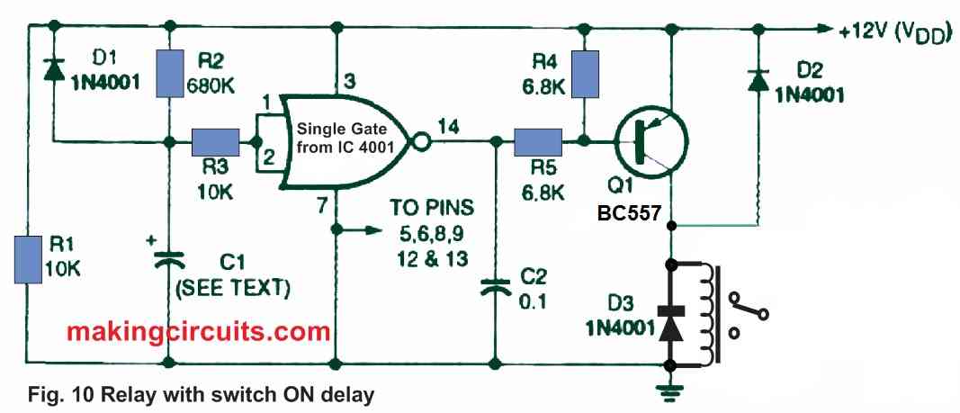
The intersection of the time-controlled voltage divider created by resistor R2 and capacitor C1 provides the input to IC1. Capacitor C1 is thoroughly discharged before power is switched ON to the circuit.
As a result, the inverter input is grounded, so that its output becomes equal to the positive supply voltage; in this arrangement, transistor Q1 and relay RY1 are both turned off.
When the circuit is powered up, C1 charges up via resistor R2, and the exponentially growing voltage is supplied to the CMOS inverter gate's input. This voltage increases to the CMOS inverter gate threshold level after a time delay specified by the RC time constant values of capacitor C1 and resistor R2.
The output of the gate then goes below zero volts, turning on transistor Q1 and relay RY1. The relay will then stay on until the circuit is turned off. The process is completed when capacitor C1 discharges rapidly through diode D1 and resistor R1.
Figure 11 demonstrates how to transpose the circuit function of Figure 10 such that the relay switches on as soon as the power is provided however shuts off after a predetermined interval. Changing the relay-driving step for an NPN transistor yields this result.
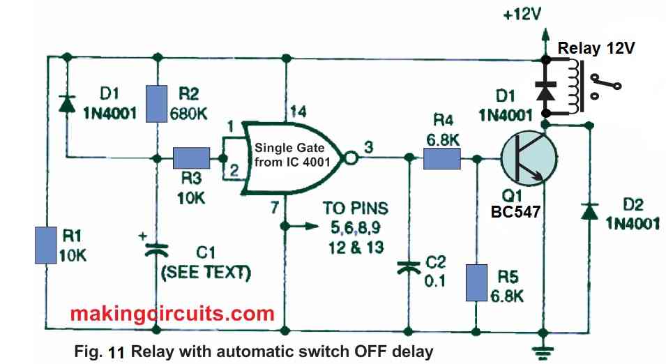
It's important to note that for every microfarad increase in the amount of capacitor C1, the circuits in Figs. 10 and 11 create a new delay of around 0.5 seconds. This allows for delays of up to a few minutes. If needed, the delay intervals could be varied by substituting resistor R2 with a series of constant and variable resistors with minimum values close to that of resistor R2.
Figure 12 demonstrates how a pushbutton-activated one-shot multivibrator relay-switching circuit may give delays of up to many minutes with good precision using a couple of CMOS gates. When START switch S1 is pushed, the relay is activated.
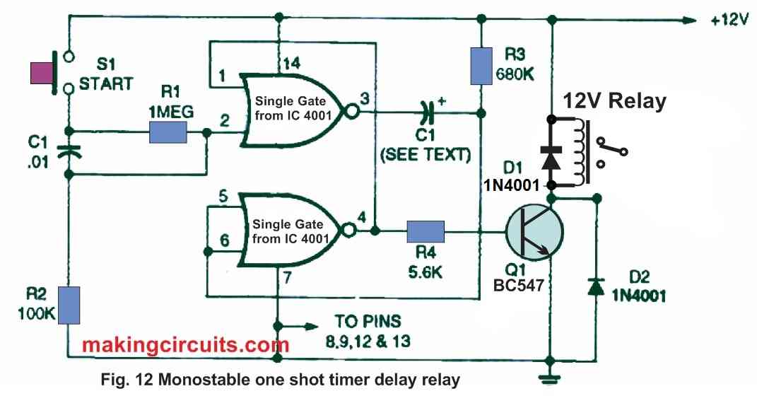
It does, however, automatically switch off after a programmed period of around 0.5 seconds per microfarad of capacitor C1 value. The couple of CMOS gates are set up as a manually activated monostable multivibrator, with R4 and transistor Q1 feeding the output to the relay.
The circuits in Figures 10 to 12 are all built around the basic CMOS gates and are designed for applications that do not demand great timing precision. Circuits centered around the 555-type timer IC may achieve far better timing precision.
In Fig 10 the pins 3 and 14 are reversed. 14 should go to +Vdd and 3 goes to R5 and C2 Ather than that the circuit works like a charm.
OK, thank you so much for pointing the silly mistake, I hope the other readers will note this and do the necessary corrections in their design.