• Skip to main content
  • Skip to primary sidebar

Making Easy Circuits

Learn and build electronic circuits

You are here: Home / Sensors and Detectors / Simple Shadow Sensor Alarm Circuit

Simple Shadow Sensor Alarm Circuit

Last Updated on January 13, 2025 by Admin Leave a Comment

Utilizing two LDRs, the mentioned shadow detector circuit efficiently detects variations in light intensity and sounds a loud warning siren.

The method of detection might not be as precise in circuits that just employ one LDR (photoresist) as it is with the two LDRs covered here.The following is a study of the shadow detector circuit's operational details:

The active operational amplifier, that acts as a comparator, and the two LDRs are the circuit's essential components.

How a Circuit Works

As can be seen from the diagram, the opamp's inputs are meticulously balanced by means of resistors and alternatively placed LDRs across the matching supply rails.

Presets might be used in lieu of the two resistors to provide an intricate modification alternative, guarantee ideal balance, and provide exact zero logic at the opamp's output.

A low logic level is produced at the IC's output when there is normal illumination, meaning when there is no shadow or shade and the two LDRs are able to catch an equal quantity of light through the opamp's sensing input.

The logic at the IC's output switches to a non-inverting logic whenever one of the LDRs (for example, R1) encounters a shadow with a smaller amount light compared to the other (R4), which lowers the voltage at the opamp's inverting input.

Transistor Q1 is activated by the aforementioned event, and the LED and relay are subsequently activated. Whenever the relay turns on a siren, the LED enables the acquisition of an optical prior warning.

To shield the transistor Q1 from the relay backward EMFs, it might be preferable to connect a semiconductor diode (D1) alongside with the relay, as indicated in the diagram.

Circuit Diagram

Shadow Sensor Alarm Circuit

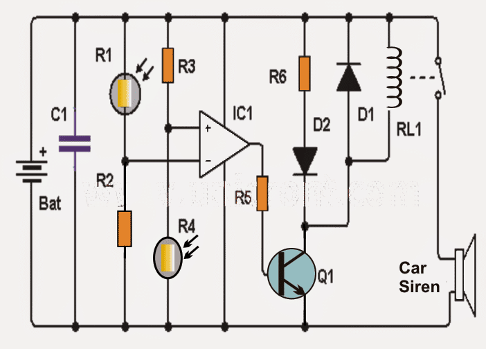
Notes: - The circuit is supplied by a 9 volt lead acid battery or any equivalent SMF battery. - In order to get most effective responsiveness and to prevent improper switching, the LDRs must be positioned around 3 cm apart.

Parts list for the proposed shadow detector circuit

QuantityComponent DescriptionDesignation
1Operational amplifier: LM741IC1
2LDRs (photoresistor / LDR)R1, R2
1NPN transistor 2N2222 or similarQ1
11N4007 diodeD1
1Red LED diodeD2
19 volt relayRL1
210K resistorsR3, R4
11K resistorR5
1470 ohm resistorR6
1100 nF capacitorC1

You'll also like:

  • 1.  How to make a Proximity Detector Circuit Using IC 555
  • 2.  Gas Sensor Circuit
  • 3.  How to Make a Simple Shadow Detector Circuit
  • 4.  Magnetic Proximity Switch Circuit
  • 5.  Ferrous, Non-Ferrous Metal Detector Circuit
  • 6.  Seismic Sensor Circuit

About Admin

Hey friends, Thanks a bunch for stopping by this site! I am an engineer with a Bachelor of Engineering in Electronics and Telecommunication. One of my passions is gathering information from all sorts of electronics books and tutorials. I then take that information and compile it into a language that is super easy to understand. My goal is to make those complex electronics circuit concepts and technical terms much more accessible for all the new and budding electronics engineers out there. I can also design customized circuit diagrams as required by the users.
If you have any questions related to this field, please do not hesitate to drop a comment! I am always here and ready to help you out with any queries you might have. I cannot wait to hear from you!

Reader Interactions

Leave a Reply Cancel reply

Your email address will not be published. Required fields are marked *

Primary Sidebar

Categories

  • 3 Phase (4)
  • 8051 Microcontroller (1)
  • Arduino (11)
  • Audio and Amplifier (102)
  • Automation (8)
  • Battery Chargers (64)
  • Bicycle Projects (4)
  • Car and Motorcycle Projects (39)
  • Datasheets (10)
  • DIY Projects (5)
  • Electrical (15)
  • Free Energy (6)
  • Games Projects (2)
  • High Voltage (14)
  • Hobby Projects (30)
  • Household Circuits (2)
  • IC 555 Circuits (4)
  • Ignition Circuits (2)
  • Indicators (50)
  • Infrared (6)
  • Inverter Circuits (29)
  • Lights and Lamps (97)
  • Medical (8)
  • Meter and Tester Circuits (38)
  • Motor Driver (17)
  • New Circuits (56)
  • Oscillators (30)
  • Pets and Pests (5)
  • Power supply (81)
  • Protection Circuits (25)
  • PWM (8)
  • Remote Control (20)
  • Security and Alarm Circuit (48)
  • Sensors and Detectors (66)
  • Signal Processor (23)
  • Solar Controller Circuits (61)
  • SSR (3)
  • Temperature Controller (20)
  • Timer (25)
  • Transformerless (7)
  • Transmitters (12)
  • Tutorials (45)
  • UPS (2)
  • Voltage Regulators (57)
  • Water Sensor and Controller (29)
  • Home
  • Privacy Policy
  • Contact
  • Disclaimer
  • Copyright

© 2025 · Making Easy Circuits