Basically in this article we will understand the nitty-gritty of how to get a triac to do its thing, plus we'll chat about the right way to hook up all its terminals.
Triacs are like these solid-state, two-way thyristors. They're experts when it comes to operating a load on and off in both directions of an AC signal, whether it's a 120-volt or a 240-volt AC power setup.
You can get a triac to turn on (we call that "activating" or "latching") whenever you want on the AC line, whether it's in sync or totally random.
But if the current flowing into the triac's gate terminal dips below this super low threshold (its "lowest holding threshold"), the triac will switch off super quick, like at the very end of each AC half-cycle (that's 180 electrical degrees).
WARNING: Heads up, folks! All the circuits we are gonna talk about involve playing with some seriously dangerous 220 V AC mains. So you gotta be extra, extra careful when you're using and testing these circuits. Make sure you're taking all the necessary precautions. Seriously these circuits are really only meant for the pros.
Synchronous vs. Asynchronous Switching
Okay so when we talk about "asynchronous switching," we mean the triac is kinda just turning on whenever it feels like it during the phase cycle.
Now because of this randomness, asynchronous triac switching can cause a bunch of radio-frequency interference (RFI), especially when it first kicks on.
But with "synchronous triac switching," things are way more organized. The switching happens at the exact same moment for each AC half-cycle (usually right after the zero-crossing bit), which means it barely makes any RFI.
Just so you know, all the circuits we are showing you here use asynchronous power switching. Figures 1–8 show off a bunch of asynchronous triac power-switching circuits for turning AC lines on and off in a simple way.
How to Connect a Triac
A triac's got three main hookup spots which are MT1, MT2, and the Gate. The "MT" stands for "main terminal."
So basically, the main terminals MT1 and MT2 are what you use to switch those big, heavy AC mains-operated loads using either a 220V or 120V AC mains supply.
And this switching action happens when you send a little DC voltage to the triac's gate terminal.
Now a lot of newbies get tripped up and ask, "How do I hook up the MT1 and MT2 terminals with the AC load, and what about sending DC to the gate?"
Heres the golden rule: to hook up the triac MT1 and MT2 terminals the right way, always make sure the AC load is wired in series with the MT2 terminal. Then connect the MT1 straight to the other AC line of the mains supply.
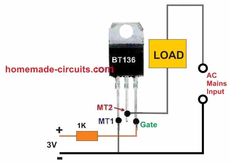
So when you’re dealing with the AC line thats hooked up to the MT1 terminal of a triac, you gotta make sure that it is also connected to the negative or ground line of the DC power supply that you're using to trigger the triac's gate.
If you skip this step, then triac won’t even respond to those gate signals and that’s a big no-no!
Triac Switching
Now if we check out Figure 1, we can see a basic setup for an AC power switch using a triac. This little circuit is super handy because it can control AC power flowing to all sorts of stuff like lamps, heaters, motors, and a bunch of other gadgets.
But you need to make sure that the triac you are using can handle the right amount of power for whatever application you have got going on. It is all about making sure it can reliably switch that AC power without any hiccups.
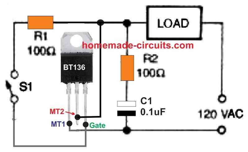
So all the parts you see in the schematics in this article? They were hand-picked to only switch 120 volts AC at 50/60 Hz. Gotta keep those specs in mind!
Now when the switch labeled S1 is open, the triac turns off and acts like an open switch. Basically it’s off and not letting any power through.
But when you close that switch S1, things change! It starts acting like a closed switch that gets its power straight from the AC mains line through the load and resistor R1. This happens right at the beginning of each AC half-cycle.
Once the triac turns on, its main terminal voltage drops down to just a few hundred millivolts. Because of this R1 and S1 dont really draw much current.
And remember that when S1 is first closed, the triac's turn-on threshold is not synced up with the AC line right away. But don’t worry, it gets in sync over the next few AC half-cycles. It just needs a moment to find its groove!
Okay so the snubber network, made up of resistor R1 and capacitor C1, is there to reduce those voltage spikes that can pop up when you are switching inductive loads or when the current and voltage are not playing nice together (out of phase).
Most of the triac circuits we are chatting about in this article use these snubber connections. They’re like the safety nets of the circuit world!
Basically the triac works like a power switch that you can control with a DC supply derived from the AC supply, as shown in Figure 2. It is like using the AC power to create a little DC controller for the triac!
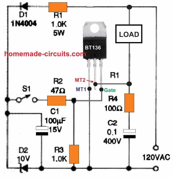
So in each positive half-cycle of the AC line, the capacitor C1 gets charged up to +10 volts through resistor R1 and that Zener diode, D1. It's like a little energy boost happening every half-cycle!
When you flip switch S1 to the ON position, the stored-up charge from C1 gives the triac the kickstart it needs. Now here's a thing to keep in mind: resistor R1 is always exposed to pretty much the full AC line voltage.
Because of this it needs to be able to handle a good amount of power. In our example we are talking about a 5-watt rating. You do not want that thing burning out on you!
Now because every part of this circuit is "active," it can be seriously dangerous and give you a nasty, potentially fatal, electrical shock. So gotta be super careful!
Plus since this circuit does not have an isolator or some kind of complementing mechanism, it is kinda hard to hook it up with other external control circuits. It is a bit of a loner in that sense.
Isolated Triac Control using Opto-Couplers
But don't worry, we have got a fix for that. If you take a peek at Figure 3, you will see how we can tweak the circuit from Figure 2 to make it easier to connect with those external control circuits.
Instead of switch S1, we are using a bipolar junction transistor Q1. And Q1 is controlled by the output stage of an optocoupler (or optoisolator), IC1. Think of it as a remote control for the transistor!
This system uses an infrared light-emitting diode (IRED) that is optically linked to a phototransistor. Any of those commercially available transistor-output optoisolators will work just fine in this setup. It is all about keeping things isolated and safe while still getting the job done!
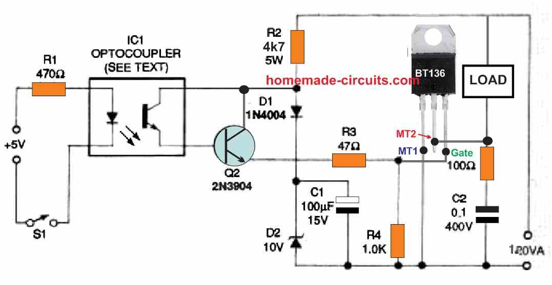
So when we are talkin' optocouplers, we have got a bunch of options like TIL111, TIL 112, 4N27, and 4N28, just to name a few. And to power these optocouplers, you can use a 5-volt or larger DC source with the help of resistor R1. It is like giving them a little juice to do their thing!
The triac only switches on after switch S1 connects the input circuit supply to a 5-volt or larger power source. So basically S1 is the key to unlocking the triac's power!
Now here's where things get interesting. Optocouplers usually have isolation values (Viso) around 5000 volts AC and some can even handle up to 7500 volts AC! That is some serious protection!
What this means is that the DC input circuit is completely isolated from the triac output side circuit which is powered by the AC line. It is like having a super strong barrier between the two sides, keeping everything nice and safe.
But you can swap out S1 with a cool electronic detector to turn this basic triac switching circuit into an automated "remote" triac switcher. How neat is that?
And to show you what I mean, Figure 4 is basically a tweaked version of the circuit we saw in Figure 3. It is all about making things even more versatile and easy to control!
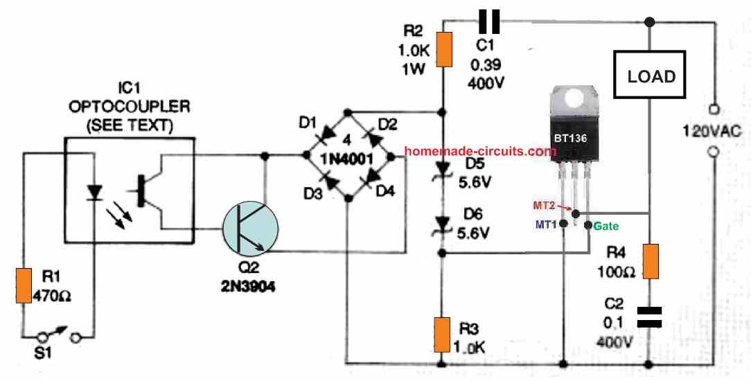
Alright, so in this setup the triac gets its AC power boost every half-cycle of the AC line and that is all thanks to capacitor C1 resistor R1 and those back-to-back Zener diodes D5 and D6. Basically C1 and R1 are hanging out with those Zener diodes D5 and D6 and they are making sure the triac gets triggered with each AC half-cycle.
Now how much current goes into the triac's gate is all up to the AC line impedance of C1 but the cool thing is C1 barely loses any power, like close to zero.
Then you have got this series thing going on with Zener diodes D5 and D6 plus resistor R3 and they are all loaded up by transistor Q1. This whole setup is connected across a bridge rectifier made from diodes D1, D2, D3, and D4. When transistor Q1 is chilling in the off position, the bridge is pretty much open, and the triac, TR1, fires up at the start of each AC half-cycle.
But once transistor Q1 jumps into action and turns on, it is like a short circuit happens across D5, D6, and R3. This cuts off the gate current to the triac which then shuts down the triac, TR1.
Transistor Q1 is getting its instructions from an optocoupler that is part of an isolated external input stage. So normally the triac is on, but it goes off as soon as the switch S1 is closed.
If you are thinking about using DC to trigger a triac, check out figures 5 and 6. They show you how to use a DC power source from a transformer power supply and a transistorized switch to get that triac AC power switch going.
When S1 is closed, the transistor and the triac both turn on. Open S1, and they both turn off. Also in Figure 5 you could swap out switch S1 for a sensor that can pick up on physical changes and react to them. Oh, and just a heads up, transistor Q1 could be a BC557 transistor but it's not in the diagram.
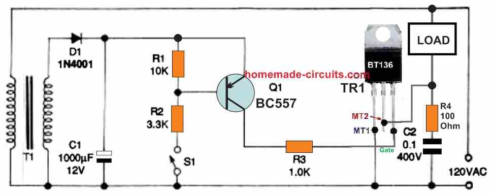
Okay, so if things get chilly and the ambient temperature dips below a set point, you could use a thermistor to kick the triac circuit into gear.
On the flip side, you could swap in a photoconductive cell to keep an eye on light levels, a pressure sensor to spot changes in air or liquid pressure or even a flow meter to react to different liquid or air flow rates. Basically lots of different sensors could be used to trigger the triac.
Now be careful, that circuit is "live," meaning it is packing a potentially lethal shock, so be super careful.
The other figure shows how to tweak the initial circuit by adding an optocoupler for control. This means the circuit can be triggered by a totally separate and isolated external circuit, all thanks to that optocoupler.
Triggering through Unijunction Transistor
Alright, so figures 7 and 8 show a bunch of different ways to trigger a triac using a completely isolated external circuit.
In these circuits, the triggering action comes from a unijunction transistor (UJT) configured in a pulse-generating relaxation oscillator. Basically the UJT is set up as a relaxation oscillator that makes the triggering pulses in both circuits.
This oscillator circuit with its UJT Q2 cranks out triggering pulses. It is running at a frequency of several kHz and sends those pulses to the triac's gate through a pulse transformer T1 which makes sure everything stays nice and isolated.
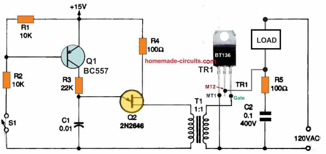
So basically when the oscillator is doing its thing in the "ON" phases, the triac gets switched on super quick, right at the very beginning of each AC half-cycle. This happens because the UJT device is pretty darn fast at its job.
Now if we add a resistor, let us call it R3 and stick it between the emitter and the base B2 of the UJT (which we are calling Q2) and then we also hook up a capacitor C1, between the emitter and the base B1 then our UJT Q2 starts acting like a relaxation oscillator.
In this setup the UJT can switch super fast to either fill up or empty the capacitor and it does this at crazy speeds as soon as the capacitor voltage hits a certain point.
We can figure out how long it takes for the capacitor to empty by using some sawtooth frequency calculations. Basically it is roughly 1 divided by the time it takes.
And because Q1 is configured in line with the UJT's main timing resistor R3 in that Fig. 7 circuit, the UJT and the triac only switch on when S1 is closed.
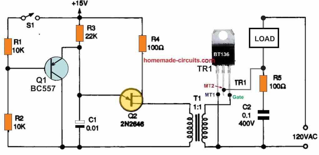
However in Figure 8 above, the UJT and triac only turn on whenever S1 is open because Q1 is connected in parallel with the UJT's primary timing capacitor C1 in the circuit.
In any of these circuits S1 might be changed to a sensor or transducer in order to execute the already mentioned automatic power-switching function.
An NPN transistor such a BC547 would be the Q1 in the above picture.
Thank you for this informative article! I dabbled with Ic 555 for a square wave generator to drive an ignition coil hooked to a spark plug on my truck exhaust after removing my plugged up catalytic converter as I wanted to burn unburnt hydrocarbons, I also made a 833A vacuum tube tesla that had a respectable 19” arc, but I has 15 years since I have done any work or play with semiconductors and I have pretty much been in the realm of 60Hz AC single phase and three phase electricity for my hobbies. My first career was commercial pipe fitting/plumbing and my second career is aircraft maintenance, but I have always wanted to be an electrical engineer, but after high school, I have had ENOUGH of my peers as I have developed agoraphobia and generalized anxiety disorder from being in school. Thank you for your article, I now have a better understanding of triacs now.
Hey Rod, you are most welcome. Glad you found the post helpful…
I appreciate your honest feedback…I think anxiety can be cured with beta blockers, you can consult a doctor regarding this…I have migraine issues and some social phobia, and use the same medicine to keep these in control…
I’m going to make a spot welder using an old microwave transformer with a few windings in the secondary to get 2-6V 250-350A to do the welding. I plan on using an Arduino to control the operation so I can adjust pulse widths, pulse power levels, and a delay between the first and second pulses. Do you have any recommended reading on how to approach that?
Don’t use a triac for controlling the PWM, instead use an MOSFET SSR as shown below, and then you can simply use a 555 based PWM controller to control the max power of the welding…
https://www.homemade-circuits.com/wp-content/uploads/2025/11/single-mosfet-SSR-circuit-1.jpg
I’m almost eighty now. Ever read the “cookbooks” by Don Lancaster? I’m trying to hook up a 3-speed fan on a wood stove so it goes faster as the temp goes up. I used 555 chips for everything back when. I’m trying to find a clever way so as each switching temp is reached, the circuit shuts off one triac and turns on the next one. I’d hate having to learn another microcomputer and relearn C++. I like the 6800 and assembler.
Hey David, there’s no need to learn C++ or Arduino for this simple operation, it can be simply done using the IC LM3915.
Let me know if you want me to design this circuit for you??
I’m using your first/simplest circuit with BT 136 triac. It switches with 2.5 V + on the gate from a bench supply. I’m using a rainbird transformer with 28VAC output for my AC source. Except for the O-Scope nothing is grounded. I get 1/2 wave on the load (50 ohm resistor) I tried a different triac, same results
Terry
Please connect an incandescent bulb in place of the load and check its brightness…. check if it is the same when it is connected directly with the mains AC source, if yes, then the triac is conducting fully for both the AC cycles…
If possible please use 5V or 12V DC for the gate.
Make sure the MT1, MT2 connections are correct…