In this post we learn how to make a simple wheel RPM meter circuit for calibrating the RPM in crucial machines which require precise RPM settings.
All types machine wheel will have a standard rated speeds (RPM) at which they are supposed to be operated. For example let's take the example of a wheel rated for 33 rpm. In such a case a slight variation in the rpm of this wheel could cause poor end result. In ordinaery machines a rubber and a brass pulley might be used for the drive. This system could wear away with age and hence results in slight variations in speed. It is diflicult to detect these variations with the naked eye. This prposed wheel RPM meter circuit measures the rpm of the record player so that the necessary changes in the speed can be made as per the requirements. The major advantage of this gadget is that it does not require any standard rpm source for calibration. It straightway gives the rpm reading on the digital display board. The "U" shaped wooden block (see fig), having an LDR and a lamp, is used as the rpm sensing device.

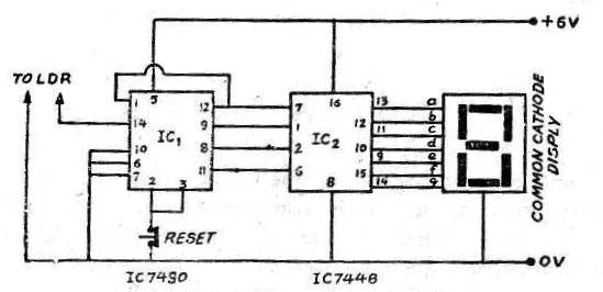
The LDR and the lamp are fixed on to the opposite sides of the block as shown in the figure. Under ordinary conditions, the light emitted from the bulb keeps the LDR illuminated An LDR when illuminated properly offers a very small resistance (few hundred ohms). A flat circular plate, with a small projection at its periphery is cut out from a card board sheet. This is then placed on to the shaft of the wheel in place of the actual wheel, The RPM of the machine is set at a speed which is to be tested and then the supply to the player is
switched on, The rpm sensing unit is placed in a position such that the projection in the card board record interrupts the light falling on the LDR at each rotation. Thus on completion of each rotation the light falling on the LDR is interrupted. The LDR is connected to the trigger (pin 14) of the decade counter. The pulses for IC 7490 decade counter are generated hy the LDR which depend upon the speed ofthe record player. The counter counts the number of pulses received to the maximum of 9 after which it resets to zero. The second IC, IC 7448, is a b c d to g 7 segment display decoder and it, along with a 7 segment common cathode display, displays the number of ctnmts, Since there is only one 7 segment display, the counter can count only upto 9, utter which it resets to zero and again starts counting from one onwards. For 16 rpm it should cross zero once & then count 6. For 33 rpm it should cross zero thrice and then count 3. A stop watch or wrist watch is used to check the time i.e. to find out number of revolutions made by the record per one minute time.
Parts Required for the proposed simple wheel RPM meter circuit
(1) Integrated circuits :-
Ic 7490
IC 7448
(2) 7 Segment cnmmon catlmdn display.
(3) Push—On Switch 1no
(4) LDR 1no
(4) Bulb
(6) Wooden block, Card board with projection (see tcm).
Leave a Reply