• Skip to main content
  • Skip to primary sidebar

Making Easy Circuits

Learn and build electronic circuits

You are here: Home / New Circuits / Simplest White Noise Generator Circuit

Simplest White Noise Generator Circuit

Last Updated on November 19, 2021 by Admin Leave a Comment

An interesting yet simple waveform generator is the "white noise" generator circuit. When summed over a unit of time, this is a waveform that encompasses a whole range of randomly produced frequencies, each with identical mean energy. White noise could be used to test audio and radio frequency amplifiers, and it's also commonly employed to obscure background noise to facilitate sleep.

The concept for a basic, workable white-noise generator is shown in the figure below. It works on a theory which assumes that all reverse-biased Zener diodes can produce white noise by default.

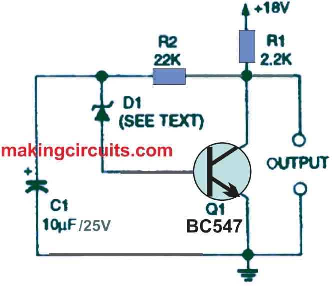
R2 and 131 are interconnected in a negative-feedback loop between the collector and base of the common-emitter amplifier Q1 as shown in the above figure. The generator's DC operating thresholds are stabilized by negative feedback.

Capacitor C1 is used to disconnect the circuit from ac voltage. In series with the base of transistor Q1, the Zener diode works as a white-noise generator.

The Zener noise is amplified to a theoretical level of roughly 1 volt peak-to-peak by the transistor. This design would work with any Zener diode (D1) specified with a value between 5.6 V to 12 V.

You'll also like:

  • 1.  Easy 1.5V to 12V/24V Converter Circuits
  • 2.  How to Make Pierce Oscillator Circuits
  • 3.  High Low Temperature Alarm Circuit using Transistors
  • 4.  Dry Run Protection for Motor using Reed Relay Switch
  • 5.  Adjustable Noise Generator Circuit
  • 6.  12 Best Oscillator Circuits Explained

About Admin

Hey friends, Thanks a bunch for stopping by this site! I am an engineer with a Bachelor of Engineering in Electronics and Telecommunication. One of my passions is gathering information from all sorts of electronics books and tutorials. I then take that information and compile it into a language that is super easy to understand. My goal is to make those complex electronics circuit concepts and technical terms much more accessible for all the new and budding electronics engineers out there. I can also design customized circuit diagrams as required by the users.
If you have any questions related to this field, please do not hesitate to drop a comment! I am always here and ready to help you out with any queries you might have. I cannot wait to hear from you!

Reader Interactions

Leave a Reply Cancel reply

Your email address will not be published. Required fields are marked *

Primary Sidebar

Categories

  • 3 Phase (4)
  • 8051 Microcontroller (1)
  • Arduino (11)
  • Audio and Amplifier (102)
  • Automation (8)
  • Battery Chargers (64)
  • Bicycle Projects (4)
  • Car and Motorcycle Projects (39)
  • Datasheets (10)
  • DIY Projects (5)
  • Electrical (15)
  • Free Energy (6)
  • Games Projects (2)
  • High Voltage (14)
  • Hobby Projects (30)
  • Household Circuits (2)
  • IC 555 Circuits (4)
  • Ignition Circuits (2)
  • Indicators (50)
  • Infrared (6)
  • Inverter Circuits (29)
  • Lights and Lamps (97)
  • Medical (8)
  • Meter and Tester Circuits (38)
  • Motor Driver (17)
  • New Circuits (56)
  • Oscillators (30)
  • Pets and Pests (5)
  • Power supply (81)
  • Protection Circuits (25)
  • PWM (8)
  • Remote Control (20)
  • Security and Alarm Circuit (48)
  • Sensors and Detectors (66)
  • Signal Processor (23)
  • Solar Controller Circuits (61)
  • SSR (3)
  • Temperature Controller (20)
  • Timer (25)
  • Transformerless (7)
  • Transmitters (12)
  • Tutorials (45)
  • UPS (2)
  • Voltage Regulators (57)
  • Water Sensor and Controller (29)
  • Home
  • Privacy Policy
  • Contact
  • Disclaimer
  • Copyright

© 2025 · Making Easy Circuits