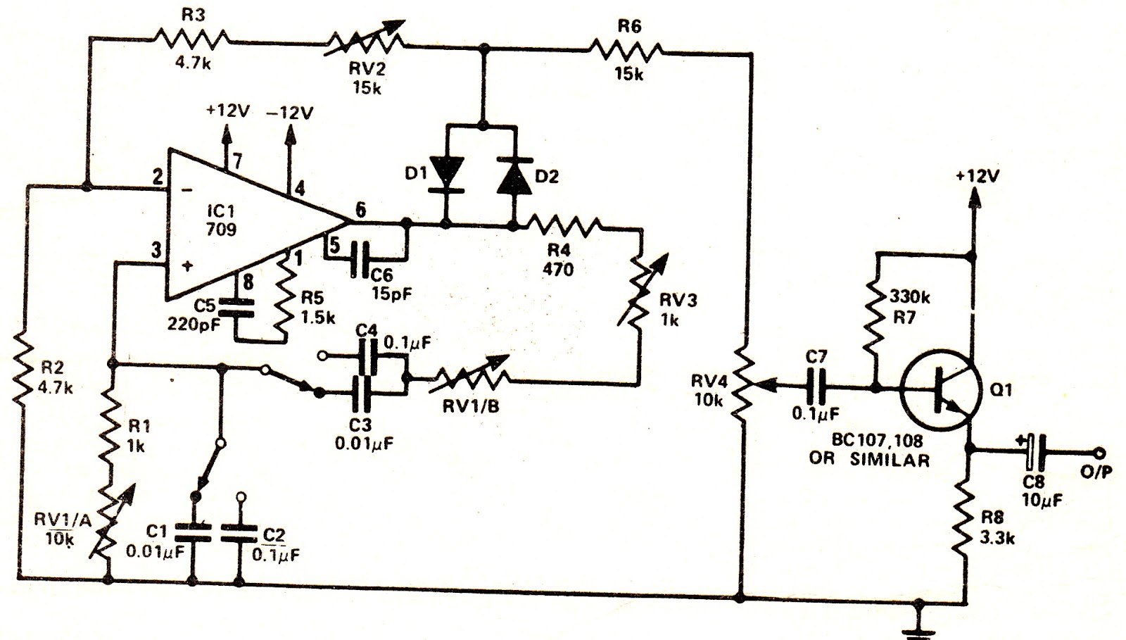
This simple oscillator circuit can be used to generate symmetrical sine wave frequency output.
To maintain oscillation the op. amp. must have a gain equal or exceeding this attentuation which is in fact x3.
The desired gain is obtained by selecting the ratio of feedback resistance to input resistance of the inverting input (RV2 + R3)/R2.
If the overall gain, including feedback, exceeds unity the circuit will produce sine wave oscillation at a frequency set by the Wien network.
How the circuit Works
Stabilization of the gain is brought about by the action of diodes D1 and Dl% then the instantaneous output voltage is close to zero, neither diode conducts, since even a germanium diode requires 0.4 volts or so forward voltage to bias it on.
Consequently, the negative feedback loop is open (giving maximum gain) and, under the action of the positive feedback via the Wien network, oscillations build up rapidly.
As soon as their amplitude is sufficient to bias on either D1 or D2 (depending on the polarity of the output voltage swing), then R2, R3 and RV2 provide negative feedback, so limiting oscillations to a convenient level.
Reinforcement of such oscillations takes place close to each zero crossing when D1 and D2 are open non·conducting; the setting of RV2 determines the final amplitude.
This method of stabilization does give rise to a very small amount of crossover distortion, but the effect of this can be minimized by setting VR2 for the largest possible sine wave without clipping.
In any event, some distortion is a small price to pay for such a simple, easy-to~get—working sine wave oscillator and, further, it is a low level of distortion, some class B audio amplifiers are worse!
Range switching is confined to a choice of two ranges, in the interest of simplicity and cheapness, but more ranges could easily be provided if the constructor is so inclined.
A simple emitter follower output stage completes the unit, with a logarithmic potentiometer as a level control, enabling the output to be set from 1 V rms down to 10 mV rms or so.
With wiring up completed and thoroughly checked, switch on and, if possible, monitor the output on an oscilloscope. No ’scope? Then a pair of headphones, of reasonably high impedance, can be used instead.
Set RV4 about half way, S1 to "low" and RV1 about half way. If there is no output, adjust RV2; clockwise rotation should give increased output.
With an ac meter, measure the signal level at the junction of D1, D2 and RV2. Adjust RV2 for 3 volts rms.
This will ensure the highest output level (thus reducing the effect of crossover distortion) consistent with sine wave operation (no`clipping). This should provide about one volt rms at the output.
Leave a Reply