A couple of very basic and small FM transmitter circuits has been discussed in this article, using a single transistor transmitter circuit, which is small yet is able to communicate over a distance of around 100 meter.

1) FM Transmitter Circuit Description
The offered system enables us to generate an FM transmitter, which includes an amplified microphone circuit, with compact dimensions (23 × 41 mm) that functions within a frequency range between 70 and 110 MHz. It could be picked up by a straightforward FM receiver a few tens of yards apart.
To be able to enhance the range, you should implement at point A a piece of 75 cm long wire that has an antenna function. Just one 9 volt battery is sufficient to power the device. The consumption is 5 mA only.
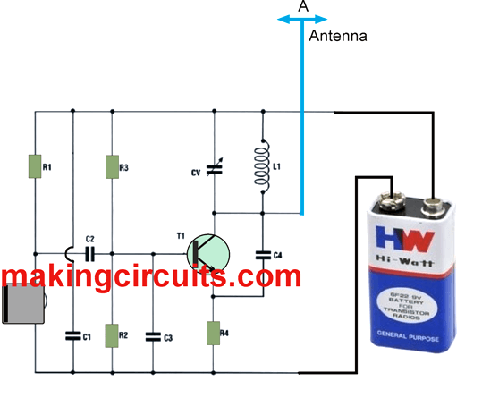
For your set up of the components it really is adequate to follow along with cautiously the clues of the layout diagram.
Parts List for the proposed small FM transmitter circuit
All resistors are
Of 1/4 watt except if mentioned otherwise
R1 = 10 K
R2 = 10 K
R3 = 68 K
R4 = 120 Ohms
CI 100 nF .
C2 = 47 nF .
C3 = 470 pF .
C4 = 3.3 pF .
CV1 = 4- 20 pF trimmer.
L1 = 0.6 μH coil.
T1 = 2N2222
M = Electret MIC.
1 Clip for 9 volt battery.
Technical specifications :
POWER SUPPLY: 9V Battery PP3
Power consumption: 5mA
FREQUENCY: 70-110 MHz
Distance Range: Over 100 meters
Design#2 200 Meters Transmitter Circuit
Referring to the circuit diagram below, an electret microphone picks up sounds from the surroundings, which Q1 amplifies. Q1's DC operational bias is adjusted by resistors R2-R5. C3 improves the AC response to the audio voltage, while C2 blocks the DC bias and links the AC to the next stage, which is where the RF action occurs. Q2's base receives the enhanced AC voltage from Q1.
The oscillator is made up of the transistor Q2 and its related circuitry (C5 and the inductor) that works between 80 and 130 MHz.
Because the oscillator is voltage-controlled, the audio voltage delivered to Q2's base modulates it. The input to the RF stage is limited by resistor R6, whose value may be modified as needed to restrict the loudness of the input. This will allow you to keep the level of distortion on too loud inputs under control.
The DC operational bias of Q2, an additional 2N2222 that serves as the transmitter's oscillator and modulator, is adjusted via resistors R7-R9. C5 is a 6-50 pF trimmer capacitor that tunes the oscillator tank circuit, while C4 sends the RF from the oscillator to ground to keep it stable.
How to Build
This 200 meter range FM transmitter circuit is made out of perforated building board with 0.1-inch spacing between holes. Part spacing isn't important, but part location is. You should arrange the parts on the pcb in a pattern that resembles the schematic. In general, you'll would like the transmitter to be as tiny as feasible. You may begin on the left side of the diagram and work our way to the right.
You'll need a strip of perfboard which is 12 holes broad and 30 holes long. That way, you'll have more than enough area to play with while still producing a compact item. To begin, use bare wire to create two power supply lines on the board: the positive supply from the battery would be on upper edge, and the negative (ground) should be on the bottom edge of the board.
The bias voltage for the microphone is provided by a 1K resistor (R1). Ensure that you mount the resistor vertically adjacent to the positive supply line and twist the connection to the board.
Move down to the bottom bus after passing through the board. Next, connect the microphone wires to the board, being careful that the MIC's ground lead can be soldered to the ground line of the board. Solder the connection between R1 and the microphone's positive lead.
The 10 uF capacitor, C1, must be attached to the microphone/R1 junction in the center of the board, orientated as indicated on the diagram.
Hand Made Coil and Capacitor
This basic transmitter circuit just needs a couple of hand-made parts: coil L1 and capacitor C6, both of which may be manufactured just with wire and a regular pencil as a coil shape.
Two parts of 24 gauge insulated wire, arranged side by side, are wound with 6 turns around a pencil to make the inductor. Remove the coil you've created and remove the two coils from one another. The coil that looks better could be utilized in the tank circuit (L1), while the other could be used in the next one you make.
Capacitor C6, the other hand-made component, is included within the oscillator feedback. To construct this tiny value capacitor, bend a 4 -inch piece of 24 -gauge insulated wire in half and twist the wire as though it was a rope starting 1/2-inch from the open end. Finish once you have approximately 1 inch of twisted wire and cut the looped end off, keeping approximately 1/2 inch of twisted wire for the capacitor and 1/2 inch of untwisted wire for the connections.
One of the most important parts of the circuit is capacitor C7, a 0.1pF capacitor. To limit the amount of RF feedback into the remainder of the circuit, position it across the L1 - Q2 - R9 assembly, as illustrated in the circuit diagram.
Additional 24 - gauge wire must be connected to the coil you constructed, approximately 2 turns up from the bottom, or transistor side, and should be around 8-12 inches long.
Testing
To test the circuit, put in place an FM radio at least 10 feet away from the transmitter circuit project to activate the unit. Locate a vacant space on the dial and crank up the volume on the radio to detect to a null point. Listen to the radio by connecting a 9-volt battery to the transmitter.
Change the tank capacitor (C5) until the receiver "quiets"; this becomes the tuned point. It's worth noting that withdrawing your palms from the transmitter detunes the circuit slightly.
To obtain the greatest reception, it's typically preferable to keep it detuned and fine-tune the radio. If you can't achieve the tuning range you want, compress the coils in the tank circuit tighter together to increase the frequency or draw them apart to reduce it.
The circuit works much better when supplied by a battery, however if you must use a wall-derived adapter DC source, make sure the ripple voltage is as minimal as possible, else the reception would generate hum.
Do you have the pcb design? I can use pre drilled pcb but it would be easier to etch a board
Extremely sorry, I don’t have the PCB design for this project currently….
No worries. It’s a simple enough circuit. Thank you though