In this post we elaborately discuss regarding the many kinds of snubber circuits using resistor/capacitor, diodes, varistors, and also learn which of these topologies is the most efficient when it comes to protecting relay contacts from sparking and fusing?
Ideally, a diode snubber is generally preferred for relays controlling DC load, while the second best are the ones that work with resistor and capacitor networks or using RC components. That said, in an AC circuit, a varistor or RC network happens to be the most effective.
Types of Surge Suppressors:
CR type Snubber
This type applies to both DC and AC circuits. However, the load impedance has to be lower than the RC circuit impedance when utilizing the relay for supplying the AC voltage. The moment the contacts open, current will flow to the inductive load through the snubber.

Let’ say the load if a motor or a Solenoid, the release time of the relay contacts will be increased.
How to Select the Resistor and Capacitor Values
You can choose a resistance value of 0.5 to 1 Ω per 1 V of contact voltage. As these values rely on many factors including the load properties and deviations in characteristics.
You can verify the values for R and C by experimenting. As the capacitor suppresses the discharge when the contacts are opened, the resistor arrests the current once the contacts are closed. So, it is recommended to choose a capacitor with dielectric strength between 200 to 300 V.
For an AC circuit, select a capacitor that has no polarity.
In case there are uncertainties regarding the ability of the chosen capacity to cut off arcing at the contact when using high DC voltages, then connect the snubber across the contacts rather than the load.
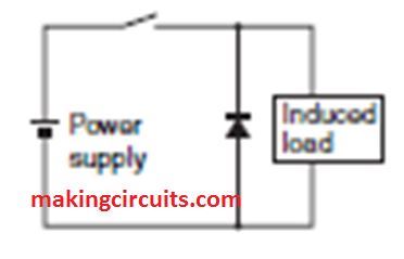
Diode type Snubber
The electromagnetic energy that is within the inductive load is channeled as current through the diode which is parallelly connected to the induced load. The current is then dissipated as Joule heat by the resistance from the load. Circuits of this type elevates the contact release time.
How to Select the Diode
A diode is placed parallel to the induced load for this type of suppressor. The electromagnetic energy stored in the inductive load will revert and dissipate itself as heat because of the diode.
This kind of suppressor increases the release time more than the RC network type.
The reason is an optimum diode has a reverse breakdown voltage of more than 10 times the circuit voltage, and a forward current larger than the rated load current.
Thus, it protects the contacts from excessive arcing when they are opening.
Diode +Zener diode type Snubber
When a Zener diode is connected in series with a diode type suppressor, the circuit will reduce the relay contact release time. Commonly, this happens in scenarios where the release time of a diode is very slow.

This type of suppressor is also not suitable for an AC circuit but good for a DC network. In terms of the breakdown voltage of the Zener diode, it is around the same value of the supply voltage.
Varistor type Snubber
This kind of suppressor is suitable for use with both AC and DC circuits. The varistor circuit avoids a high voltage from being channelled across the contacts by employing the constant-voltage properties of the varistor.
Furthermore, this type of circuit also relatively increases the release time. You can make the varistor work efficiently when you connect it across the load at a supply voltage of 28 to 48 V.
In case you have a supply voltage of 100 to 240 V, you need to connect the varistor across the contacts for effective suppression.

How to Select the Varistor Type
To select a good varistor, first, you must make sure the cut-off voltage VC is multiplied with √2. Then, the value must be checked if it is more than 1.5 times the supply voltage.
Keep in mind that setting the VC too high is not good as its efficiency will be reduced thus fails to cut off high voltages.
Do not use surge suppressors in the following combinations.
If only a capacitor is connected across the relay contacts, the setup is extremely efficient to reduce arcing. However, because of the huge electrical charge stored in the capacitor when the contacts are open, the current flows to the contacts again when they are closed. Over time, this will cause contact welding.

In another setup, the capacitor can be connected across the loads and in parallel. This configuration is very capable of reducing relay contact arcing while they are opening. On the flip side, because the charging current to C drives into the contacts when they are closed, instant contact welding may eventually occur.
Wrapping up
Normally, switching a DC inductive load is considered more difficult than switching a resistive load. But with a suitable contact protection circuit, the same level of efficiencies can be achieved with both types of load.
Great Sight Thanks: I have built a Solar Hot Water Tempering Tank System. Started with two 40 amp RELAYS one for each Element. Thus trying to control Solar Panel series voltage of 180 DC + volts and arcing is very bad. NEXT as a possible solution TWO more RELAYS on the Negative – side turning on & off along with the Positive side RELAYS. This kills the ARC but it is not instant, so over time I still get burnt contacts. What is one to do!
Would a Arc Suppressor or Snubber help? If so who sells one using 180 DC volts at 7.5 amps.
Thanks Bill
Did you try connecting a 1uF/400V capacitor right across the arcing contacts. Please try it that might help.
Question, I thought that if you put a capacitor in parallel with the relay contacts is not efficient and might result to contact welding? Should u connect also a resistor for this? Thanks vmuch
Connecting just a capacitor should also work, no need of a resistor…..
I have a automotive cooling fan that keeps killing 12v 50a relays because of arcing. The fan I’m told has an inrush of close to 35a and continuously runs at 23a. When the vehicle is running voltage is 13.8v to 14.4v. Could someone help me with the math of what value capacitor and resistor I will need to suppress the relay arcing? Many thank you’s for the help. David
Thank you for the question, I do not have the calculations with me otherwise I would have surely tried to help you.
if a .01 mfd 125 v capacitor protects a 110v 60 Hz relay
what will the size of the capacitor to adequately protect the equivalent 240v 50Hz relay contacts be ?
clearly the voltage capacity needs to be higher(perhaps 1.41 x 240) but is the capacitor size .02 mfd x 50/60 or what ?
I used to work for a company that made motor protection systems that were used in petrol pumps.
They used a 0,1uF X2 400vac capacitor in series with a 100R 0,25W carbon film resister across all the motor relay contacts. As this is a potentially explosive environment the devices required BASEEFA certification. Never had a pump explosion caused by the relays arcing, (lots of other things, but not that)!
I realize this is probably a dumb question but if I am going to ask an electrician to help I would like to understand what ought to be done. My rugby club has just retrofitted 10 new LED 750watt floodlights to replace 20 x 400 watt HPS AZMET units. The lights are controlled by a RONIS key switch LIVE on/off only. This then operates a relay which is protected by a RCD which in turn is connected to a 45 amp MCB. Turning the HPS lights on and off rarely caused the MCB to trip. With the LED lights every time they are switched off the MCB trips. Some advice I have been given suggests the Ronis switch is a slow breaker causing arcing and probably needs replacing with fast break unit . The advice also suggested de-energising of the circuit is causing surges tripping the MCB.
Apologies for the lengthy into. My question is what would I expect to see an electrician do to rectify the situation using which components. I have read your excellent paper and as I result thought it would do no harm to ask.
When any high current load is switched using mechanical switches there will be always some sparking, that cannot be avoided. So I think it is the fault of the MCB and the not the switch. You can try adding a 10uF/400V non-polar PPC capacitor right across the switch terminals and see if that helps.
Good site. One question. How is the power rating determined for the resistor. In my circuit I’m using a 1uF/200 VAC cap and 118 ohms for the resistor, The switch is hooked to a water pump.
Thanks
Thank you, since current through the resistor is very less, it can be 1/4 watt rated
I have the same question.
If the contacts are closed in a 12vdc circuit, then just as they open, there will be 12v across them and the RC in parallel with them will put 12v across the resistor in the first instant before the capacitor charges (because it is a dead short in the first instant).
To limit the current (and therefore limit the arcing on the contacts) to 1A, we need a 12 ohm resistor (12/12 = 1). 12v x 1A = an instantaneous power of 12 WATTS.
Even a 24 ohm resistor, limiting the current to 1/2a, will have to handle 6 watts.
Is the logic that it only has to handle this instantaneously, so we can “get away with” only using something like a 1/4w or 1/2w resistor?
You are correct, but the short circuit will be for a few milliseconds. So although a 1/4 watt resistor might not be reliable, perhaps a 2 watt resistor wire-wound type would have no problems at all. Alternatively you can try reducing the value of the capacitor to decrease the inrush current time.
As the article indicates, a zener snubber would not work by itself for an AC load. But if the zener were in the DC arms of a full-wave diode rectifier with the AC arms parallel to the load, the zener would see the spike as DC. The zener and full-wave rectifier approach appeals to me as the inductance of the load in my intended application will change. I would be interested if others use this approach – I do not see it published, at least on the internet.
What do you think about using two back-to-back zeners as an AC snubber.across an inductive load? Or perhaps a bridge rectifier with the AC input to the bridge across the inductive load with a single zener in the other arms of the bridge? The zeners in either case would be rated greater than 1.414 times the AC voltage.
Thanks for sharing your feedback…Your ideas make sense and should work, but the results can be verified only with a practical testing
I did in fact implement this idea. It is hard to tell as yet how successful it will be at reducing the arcing at the relay contacts, but visually it seems much less. I still have to scope it to see if spikes get through. Of course, a traditional RC snubber would work even with AC and be cheaper, but it has to incorporate the inductive load in determining the R and C values. When the inductive load is not known in advance (as in my application), maybe the zener and bridge is the answer.
Thanks for your valuable feedback, appreciate it!
Thank you for your reply and Confirming advice regarding the snubber connections..
Yours sincerely,
D Daw.
My pleasure!
I am using a double pole 30 amp relay on a 240 v a/c purely resistive circuit, ( 3 KW immersion heater) I have a couple of eBay r/c snubbers, their nicely mounted on a pc board.
I would like to use one for each pole, but undecided how to connect them.
Please advise. Thanks, DD.
You should put the snubber right across the relay contacts to which the load is connected…