In this particular submit we talk about an induction cooker/heater design which can be powered from a solar panel voltage.
According to the requirements a 500 watt output is meant to take place from a 180 watt solar panel which can not be achievable in the practical world, consequently the right solar panel parameter for the offered solar induction heating system ought to be around 600 watt, or two 180 watt panel in identical may also be attempted for optimal outcomes, this will not be inexpensive, however.
The panel specs might be varying from 30 to 44 V and the amp rating between 20 and 10 amps, and will need a buck regulator to be able to step down the voltage to the needed levels for the induction heater circuit.
An appropriate induction heater circuit can observed below which utilizes a half bridge driver topology, the schematic is fairly simple and might be recognized given below:
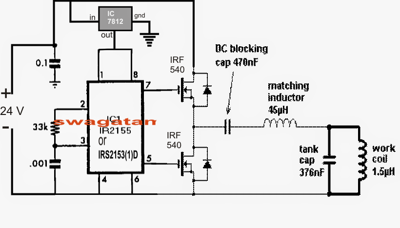
The circuit is powered from a 24 V DC supply, at current ranging up to 15 amps. A 7812 voltage regulator drops the input voltage to 12V for the driver IC which can be a regular half bridge driver IC IRS2153 or any other equivalent.
The push pull output from the IC drives a pair of mosfets which often forwards the oscillations to the main work coil of the induction heater via a DC blocking capacitor and an impedance matching inductor.
The blocking capacitor avoids too much current from transferring by means of the work coil and prevents damaging the mosfets while the inductor ensures no disturbing harmonics work out the line and induce inefficiencies into the system.
The 376 nF tank capacitors are employed to obtain a resonance with the work coil at about 210 kHz frequency which is set by the R/C network across pin2 and pin3 of the driver IC. The 33k resistor could possibly be created variable for fine tuning or optimizing the resonance effect
The work coil dimensions and the resonant capacitor arrangement are supplied in the figure below:

A buck converter for transforming the panel high voltage to the essential 24 V for the induction heater could be designed with the help of the following diagram:

T1, T2 as well as C1, C2 and the connected resistors form a classic astable multivibrator (AMV) with a set frequency of around 30 kHz.
The panel volatge is given to the above AMV and oscillated at the said frequency before feeding it to the buck converter stage created by employing a mosfet and an linked diode, inductor stage.
During the turn off periods an equivalent amount voltage is supplied from L1 in the from of back EMFs which happens to be properly filtered and provided to the linked induction heater circuit across the output terminals.
C4 ensures the transformed bucked voltage is free from any ripples so enabling in generating a cleaner DC for the induction heater circuit.
The managed 24 V DC at the outputs might be accomplished by approximately winding the proper number of turns for L1 through some trial and error as well as by the involvement of D2 which in the end stabilizes the output voltage to the essential ranges.
Leave a Reply