• Skip to main content
  • Skip to primary sidebar

Making Easy Circuits

Learn and build electronic circuits

You are here: Home / Solar Controller Circuits / Solar Panel Excess Power Dump Load Circuit

Solar Panel Excess Power Dump Load Circuit

Last Updated on March 3, 2025 by Admin Leave a Comment

Specification: Hi there, I would like to construct something that would limit the amount of electricity that a 5kW solar energy system which I now have and would like to increase may send to the grid.

The problem I've been experiencing is that we need more solar panels in the colder months, nonetheless we generate much too much power in the height of summer.

We need about 10kW of solar panels to achieve electrical independence throughout winter time because we are limited to producing 5kW of electricity.

In order in order to restrict energy transferring to maybe 4kW, I was considering using a current coil to monitor the amount of electrical energy being sent and then slowly switching in resistive loads of maybe 750W each in order to absorb excess power.

Frequency management could be used in the current system to limit solar output, however during the summer, the total power output could reach excessively large. My power supply operates at 240V and 50Hz.
I was considering flipping in resistive loads with short time intervals and load sensing the changeover.

What do you think would be a practical and, ideally, simple approach to do this?

The layout

A simple and straightforward idea might be used to fulfill the aforementioned specifications:

Solar Panel Excess Power Dump Load Circuit

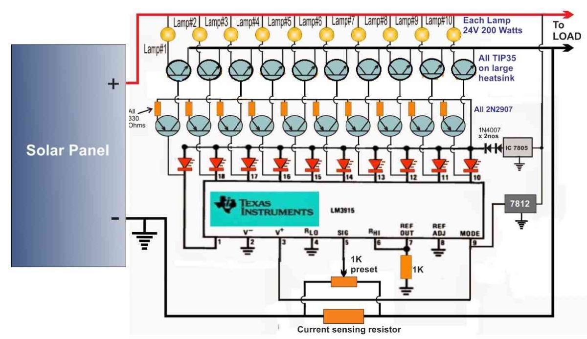
As is well known, the IC LM3915's output pins respond to a rising voltage at pin #5, which ranges from 0 to 200 mV, by successively transferring low logic throughout its 10 output pins in an expanding fashion.

To achieve the desired approach the solar panel power load dump circuit above takes advantage of the IC's aforementioned functionality.

In this article we use a current detecting resistor Rx in place of a current transformer. The formula below might be used to get this resistor's number:

Rx = 0.1 / Max current limit

The maximum current that restrict for toggling the associated dump loads may be adjusted using the preset over the Rx.

In accordance with how much current is outputting from the solar panel, the outputs of the IC turn low in a progressive and appropriate manner when the voltage over Rx rises beyond the 0.1 V level as the current export surpasses the predefined limit.

The output load current is then reduced to the intended maximum limit as a result of the dump load lights starting to illuminate and shunting the additional watts to ground.

If necessary, the lighted lights might be submerged in water to heat it, allowing the extra power from the solar panels to be applied to this purpose or any other equivalent one.

You'll also like:

  • 1.  How to Make a Simple Solar Tracker System – Mechanism and Control Circuit
  • 2.  Make this Solid-State Solar LED Street Light Circuit with Battery Protection
  • 3.  Li-Ion Solar Charger Circuit
  • 4.  How to Make a Solar E Rickshaw Circuit at Home
  • 5.  Basic Dual Axis Solar Tracker System Explained
  • 6.  Simple MPPT Circuit Simulating an Incremental Conductance Concept

About Admin

Hey friends, Thanks a bunch for stopping by this site! I am an engineer with a Bachelor of Engineering in Electronics and Telecommunication. One of my passions is gathering information from all sorts of electronics books and tutorials. I then take that information and compile it into a language that is super easy to understand. My goal is to make those complex electronics circuit concepts and technical terms much more accessible for all the new and budding electronics engineers out there. I can also design customized circuit diagrams as required by the users.
If you have any questions related to this field, please do not hesitate to drop a comment! I am always here and ready to help you out with any queries you might have. I cannot wait to hear from you!

Reader Interactions

Leave a Reply Cancel reply

Your email address will not be published. Required fields are marked *

Primary Sidebar

Categories

  • 3 Phase (4)
  • 8051 Microcontroller (1)
  • Arduino (11)
  • Audio and Amplifier (102)
  • Automation (8)
  • Battery Chargers (64)
  • Bicycle Projects (4)
  • Car and Motorcycle Projects (39)
  • Datasheets (10)
  • DIY Projects (5)
  • Electrical (15)
  • Free Energy (6)
  • Games Projects (2)
  • High Voltage (14)
  • Hobby Projects (30)
  • Household Circuits (2)
  • IC 555 Circuits (4)
  • Ignition Circuits (2)
  • Indicators (50)
  • Infrared (6)
  • Inverter Circuits (29)
  • Lights and Lamps (97)
  • Medical (8)
  • Meter and Tester Circuits (38)
  • Motor Driver (17)
  • New Circuits (56)
  • Oscillators (30)
  • Pets and Pests (5)
  • Power supply (81)
  • Protection Circuits (25)
  • PWM (8)
  • Remote Control (20)
  • Security and Alarm Circuit (48)
  • Sensors and Detectors (66)
  • Signal Processor (23)
  • Solar Controller Circuits (61)
  • SSR (3)
  • Temperature Controller (20)
  • Timer (25)
  • Transformerless (7)
  • Transmitters (12)
  • Tutorials (45)
  • UPS (2)
  • Voltage Regulators (57)
  • Water Sensor and Controller (29)
  • Home
  • Privacy Policy
  • Contact
  • Disclaimer
  • Copyright

© 2025 · Making Easy Circuits