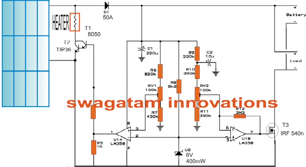
A straightforward technique for using extra solar energy from a solar panel to heat water in swimming pools, water tanks, or chicken egg chambers is described by the following solar water heater with battery charger controller circuit. In addition to powering household electrical equipment, the circuit often serves as an automated solar battery charger.
An Overview of Solar Charging
Around the world, solar energy is widely accessible and cost-free. It all comes down to installing a solar energy collector, or just a solar PV panel, and using the resource that is available.
You may have encountered a variety of effective solar battery charger circuits on this blog and on several other websites. Nonetheless, these networks often discuss obtaining electrical energy from the solar panel.
The solar voltage is stabilized by the related regulators/chargers meanwhile it is operating, making the output voltage appropriate for the linked battery, and this is typically a 12V lead acid battery.
The stabilization procedure totally ignores the surplus voltage, meaning it is either switched to ground or eliminated by electronic circuitry because a solar panel is often made to generate voltages higher than 12V, or about 20 to 30 volts.
In this article, we discover a straightforward technique for securely running appliances at home and turning extra solar energy into heat, regardless of whether a battery is being charged.
The subsequent details can help you understand how the circuit works:
Heating Water with Extra Leftover Solar Power
Suppose that the associated solar panel can produce about 24V during the hottest parts of the day in the circuit diagram for the solar water heater with battery charger controller.
A few opamps are shown in the diagram as being placed between the battery charging outlet and the solar input.
In simple terms, the left opamp is configured to let the designated charging voltage to reach its right-hand side stages.
This voltage would be something of around 14.4V for a 12V battery.
As a result, RV1 has been adjusted so that, should the input voltage over the 14.4V threshold, the opamp's output will become high.
The overcharge charge cut off stage, represented by the opamp on the far right, is in the mode of keeping an eye on the battery's charging voltage and cutting it off whenever the higher limit has been exceeded.
This happens whenever the U1B's non-inverting input detects a greater limit and turns off the mosfet's positive bias, which then in consequently switches off power to the battery that is attached.
Nevertheless, the load—basically an inverter—continues to function as it is now drawing electricity from the charged battery.
Throughout the process, in case the voltage falls merely a few volts, U1B switches back to logic high, which charges the battery yet again at the same time enabling those associated gadgets to continue operating on the common panel power.
As was said in the preceding paragraphs, U1A simultaneously keeps an eye on the display panel voltage and, like U1B, immediately changes its output to logic high as soon as detects that the voltage has risen beyond the 14.4 V limit, turning the transistors which are linked to it on.
One can notice a DC heating coil connected across the transistor's positive and collector.
The coil is switched throughout the direct solar panel voltage as the transistor conducts, which causes it to start heating up right away.
The coil's minimal resistance draws a great deal of current from the solar panel, causing the voltage to fall under the U1A threshold of 14.4 V.
In order to keep the voltage supplied to the battery inside the 14.4V range, U1A reverses the procedure and abruptly ends off the transistors' supply. The heating coil also keeps itself active during this entire procedure, allowing its heat to be used for any desired purpose.

Leave a Reply