All the spy circuits in this article are considerably strong, difficult to find in their unseen positions, and outfitted for grasping even the weakest of whispers in the vicinity. Furthermore the designs are designed for creating the selected facts upto radial distances going above 2 kms.
The above amazing features have compelled the legal authorities to enforce strict laws against the utilization of these transmitters without authorization, so prior to you making and prefer just one of these you should definitely have all the lawful formalities finished.
You may have by now discover numerous these types of incredibly simple one transistor FM transmitter circuits, in spite of this these might include particular disadvantages as I have said below:
No significant transferring range.
No improved sensitivity range
Use 1.5V for operational which perform restricted functions.
Among the very first in the line, which can be possibly the easiest is demonstrated right here circuit diagram.
Amazingly it may not utilize a MIC, rather the antenna coil by itself works a dual function of detecting sound vibrations as well as creating it into the atmosphere.
The design is invalid of a frequency figuring out stage therefore would not arrive under tuned transmitter circuits (we’ll talk about regarding these kinds of later on in the post).
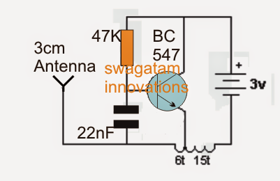
The following single transistor FM bug circuit might be known given below:
When turned on, the capacitor 22n prevents the transistor from switching until it becomes charged. A soon as this occurs the transistor switches ON via the 47k resistor making the pulse by means of the inductor which draws back a negative pulse to the base of the transistor discharging the 22n capacitor. This switches OFF the transistor until 22n one more time charges fully. The methods occur swiftly producing a frequency across the coil which happens to be transferred as carrier waves by means of the linked antenna.
In the course if the coil is exposed to an external vibrational pulse, it’s required to install the above described carrier waves in the air and might be obtained and retrieved over a regular FM radio placed and tuned at the similar frequency nearby.
The circuit could be anticipated to engage in around 90MHz frequency band.
The second instance below demonstrates an additional single transistor FM spy circuit that includes a tuned circuit or a frequency identifying phase in it. In the original prototype the coil is made by etching a spiral track layout on the PCB itself, on the other hand for optimum gain and overall performance these kinds of etched antenna coil needs to be prevented and the traditional wire wound type of coil ought to be used.

Below's one more circuit you would want to learn about. The circuit essentially utilizes the “Q factor” of the tank network accomplished from the coil and the capacitor for producing a comparatively high voltage. This stepped up potential qualities the circuit with somewhat longer selection of transmission.
For an enhanced overall performance ensure the coil and the capacitor are located as close as possible. Insert the coil leads as deep down the PCB as possible so that you can ensure it is tightly hugging the PCB. C2 value could possibly be tweaked for attaining a better choice reply from the circuit. If possible a 10pF could possibly be attempted. The coil consists of 5 turns of 1mm thick super enamelled copper wire, with 7mm diameter.

The next FM transmitter design is a bit different than the above kinds. Simply the design may very well be categorized as a common emitter type, as opposed to the others which are usually somewhat common base types with their design. The circuit employs an inductor at its base which adds a better saturation capability to the device which often permits the transistor to react in a more more healthy manner.
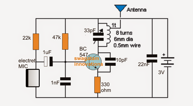
The next design in the list is a lot better than its earlier alternatives since it makes use of a slug based adjustable inductor. This permits the transmitter to be tuned by changing the slug core utilizing a screwdriver. Within this design we are able to notice the coil being connected to the collector of the transistor that enables an enormous 200 meters range to the design, with a current that could be not a lot more than 5mA. The MIC stage is isolated from the base with the aid of a 1u capacitor and the acquire of the mic could be well tweaked by modifying the series 22k resistor.
This circuit might be rated as the best as far range is concerned however it may well lack stability that may be enhanced, we’ll find out how in this article clarification.

The stableness of the above circuit could possibly be upgraded by tapping the antenna from one top turn of the coil as demonstrated in the following figure. This really improves the reaction of the circuits as a result of a number of factors. The antenna gets removed from the collector of the transistor which enables it to operate easily without needless loading, and the falling of the antenna to the top additional enables the appropriate side of the coil to get a higher stepped up voltage brought on across itself as well as the coil creating a higher attentiveness of transmission power on the antenna. Even though this enlargement may well not actual increase the range of the device, it helps make sure that the circuit will not get rattled when hand held, or when the grip is encircled close over the circuit inside its enclosure.
If you would like your bug circuit to transmit music rather than spying or eavesdropping, you might most likely find the following design fascinating. The offered FM transmitter will permit incorporating a stereo input at the same time from the source to ensure that the info contained inside both the channels enter into the air for an maximum reception. The design configuration is pretty very much like the one that’s mentioned above so would not require much of a clarification.

Examining a Two Transistor Spy Circuit
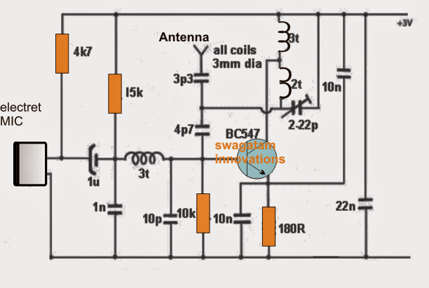
Adding a transistor stage to the above talked about single transistor FM transmitters could possibly allow the designs with significant sensitivity. An electret MiC itself has an integrated FET making it very economical and makes it a stand alone vibration amplifier device. Adding another transistor stage with it boosts the sensitivity of the device to too much to handle limits. As could be observed in the following diagram, the participation of an extra transistor stage accumulates to the gain of the MIC making the whole unit definitely delicate such that it now picks even the sound as low as a pin dropping on the floor. The extra transistor stops too much loading of the MIC thereby being sure much better effectiveness to the sensitivity.

Five issues that that can make the circuit fantastic with it reception are:
The usage of a fix capacitor in the tank circuit together with a adjustable trimmer.
A low value coupling capacitor with the MIC adequate to handle the capacitive reactance of the MIC which can be around 4k at 3kHz.
A 1u coupler is insured between the oscillator and the audio amplifier to be able to constitute for the low impedance given by the 47k base resistor.
The coil employed is wound almost making use of super enameled copper wire which guarantees greater performance than PCB etched kind of coil.
The complete circuit might be compactly designed over a small sized PCB for getting better steadiness and a drift free frequency reply.
untuk antenanya dimana kita bisa beli. antena yg 8 lilitan kawat 6mm diameter 0,5mm atau apkah bisa menggunakan antena server
The antenna can just be any small flexible wire, no need of any special antenna…
for the antenna where we can buy. antenna yg 8 turns 6mm he is 0.5mm wire
you will have to build it manually…
which capasitors to use in your schemes? what voltage? what type? I didn’t find anything about if in your guide…
All the capacitor are nonpolar, can be any type, voltage can be 25V or higher.
Hello, thank you for the good circuits and explanations you gave. I wanted to find out if I could eavesdrop on the sounds behind a wall with these circuits?
Thank you, yes it can be used to eavesdrop behind walls using an FM radio.
ola ice el transmisor y funciona joya ,cuanto alcance deberia tener alcanza +/- 20 metros el que arme ,la antena debe tener 1metro 65 cm como dice el diagrama ‘ gracias
just a 6 inches wire is enough for getting 20 meter range
muy importante el circuito num 8 espero q funcione ya q lo armare pregunta la antena tiene 1m 60cm de largo saludos
Great tutorial, ill try to do it this weekend.
my pleasure