• Skip to main content
  • Skip to primary sidebar

Making Easy Circuits

Learn and build electronic circuits

You are here: Home / New Circuits / How to make a Super Capacitor Hand Cranked Charger Circuit

How to make a Super Capacitor Hand Cranked Charger Circuit

Last Updated on February 17, 2018 by Admin Leave a Comment

The article features a basic bridge rectifier circuit which can be used for charging a bank of super capacitors by means of any appropriate hand cranked generator machine.


super2Bcapacitor


super2Bcapacitor2Bcharger2Bcircuit
The way out of the much anticipated super capacitor charger circuit is very easy, it's by utilizing a bridge rectifier for the needed DC conversion across both the cycles of the AC.
Normally we understand a bridge rectifier is set up in such a way that the associated diodes turn out to be outfitted for rectifying an AC by way of both half cycles utilized across it.
The chosen hand cranked alternator device also behaves like an AC generator wherein the forward movement of the cranking generates a forward or a positive current while the retracting action in the device does the opposite and builds up a negative current across its outputs.
In case the wires of the hand cranked generator or any generator are hooked up directly with a filter capacitor which can be a super capacitor in the existing situation would charge the capacitors during the first activity and instantly release the capacitor throughout the reverse motion of the cranking, leading to a net zero charge inside the capacitors.
When a bridge rectifier is associated across such a generator as demonstrated in the diagram, both the positive and the negative currents across its output are correctly developed into a single polarity voltage that could help to charge the super capacitors essentially without inflicting any loss across the capacitors.
I have hooked up the diagram in pictorial form, please take a look
The reverse current will matter only just in case the red/black wires are changed while hooking up with the super capacitor.... the capacitors will get harmed if the current within this situation surpasses 1 amp.
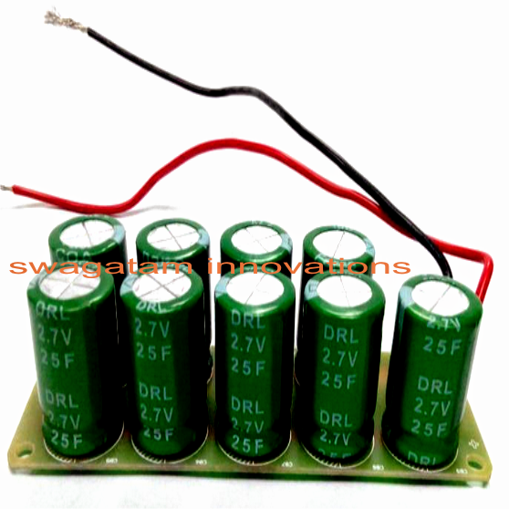
the 30 amp indicates the max current persistence in standard situations as presented in the connected picture. However it will matter only if the voltage from the generator is likely to go beyond the max voltage rating of the super capacitor..if it continues to be within the capacitors voltage range the forward current limit turns into unimportant and might be disregarded....so make sure you verify the generator's maximum voltage, it ought not become more than 24 V for the mentioned super capacitor module.
The diodes in the bridge could possibly be 1N5408 for being sure total safety to the system.
The super capacitor may be charged/discharged at will thousands of times regardless of any measures or care.

You'll also like:

  • 1.  How To Design Simple Power Supply Circuit
  • 2.  How to Change Fluorescent Tubes to LEDs
  • 3.  Simple Xenon Tube Stroboscope Circuit
  • 4.  Simplest Transistor Running Light Circuit for Christmas Lighting Decoration
  • 5.  How to Make a Cellphone Jammer Circuit Explored
  • 6.  Water Temperature Controller Circuit for Central Heating Systems

About Admin

Hey friends, Thanks a bunch for stopping by this site! I am an engineer with a Bachelor of Engineering in Electronics and Telecommunication. One of my passions is gathering information from all sorts of electronics books and tutorials. I then take that information and compile it into a language that is super easy to understand. My goal is to make those complex electronics circuit concepts and technical terms much more accessible for all the new and budding electronics engineers out there. I can also design customized circuit diagrams as required by the users.
If you have any questions related to this field, please do not hesitate to drop a comment! I am always here and ready to help you out with any queries you might have. I cannot wait to hear from you!

Reader Interactions

Leave a Reply Cancel reply

Your email address will not be published. Required fields are marked *

Primary Sidebar

Categories

  • 3 Phase (4)
  • 8051 Microcontroller (1)
  • Arduino (11)
  • Audio and Amplifier (102)
  • Automation (8)
  • Battery Chargers (64)
  • Bicycle Projects (4)
  • Car and Motorcycle Projects (39)
  • Datasheets (10)
  • DIY Projects (5)
  • Electrical (15)
  • Free Energy (6)
  • Games Projects (2)
  • High Voltage (14)
  • Hobby Projects (30)
  • Household Circuits (2)
  • IC 555 Circuits (4)
  • Ignition Circuits (2)
  • Indicators (50)
  • Infrared (6)
  • Inverter Circuits (29)
  • Lights and Lamps (97)
  • Medical (8)
  • Meter and Tester Circuits (38)
  • Motor Driver (17)
  • New Circuits (56)
  • Oscillators (30)
  • Pets and Pests (5)
  • Power supply (81)
  • Protection Circuits (25)
  • PWM (8)
  • Remote Control (20)
  • Security and Alarm Circuit (48)
  • Sensors and Detectors (66)
  • Signal Processor (23)
  • Solar Controller Circuits (61)
  • SSR (3)
  • Temperature Controller (20)
  • Timer (25)
  • Transformerless (7)
  • Transmitters (12)
  • Tutorials (45)
  • UPS (2)
  • Voltage Regulators (57)
  • Water Sensor and Controller (29)
  • Home
  • Privacy Policy
  • Contact
  • Disclaimer
  • Copyright

© 2025 · Making Easy Circuits