So here we are talking about a very simple, completely transistor-based solar switching buck converter circuit. What it does is, it takes an input from 40V to 60V and converts it into any lower voltage that we want. But this is done super efficiently, so there is very little loss in conversion. Now, Mr. Daryl asked for this idea, so we are discussing it here.
Technical Details
Now what we need is a DC-DC buck converter and it should have these features:
Input voltage → It should handle anywhere between 40V and 60V DC.
Output voltage → It should be fixed at 12V, 18V, or 24V but not all together. We can make separate circuits for each output if needed.
Output current capacity → It should give at least 5A to 10A.
Protection → It should be safe from overcurrent and short circuit problems.
LED indicator → If we can have a small LED just to show that the unit is working, it would be nice.
Now Daryl is asking for help with designing this circuit.
Circuit Working
So here is the buck converter circuit we are talking about. Let us break it down in a way that is easy to understand.
We can divide the whole thing into two main parts:
Astable Multivibrator (AMV) section
MOSFET-based buck converter section
Now in the first part we have T1 and T2 which are normal BJTs and they are wired as an AMV circuit. This AMV produces a high-frequency oscillation of around 20kHz to 50kHz.
Then we have Q1 which is a MOSFET, along with L1 and D1, forming a basic buck converter stage. This stage is responsible for reducing the voltage and producing the required low voltage across capacitor C4.
Now how does it all work?
The AMV gets power from the 40V input and starts oscillating.
This oscillation is fed into the MOSFET's gate which makes the MOSFET switch ON and OFF very fast.
When this happens the current flows through L1 and D1, creating a stepped-down voltage across C4.
This is how we get the required low voltage.
But wait we do not want this voltage to go beyond a certain limit, right? That is where D2 comes in. It makes sure that the bucked voltage never goes over 30V.
Now to get the final required voltage, we use an LM396 voltage regulator. This regulator takes the 30V max bucked voltage and adjusts it to the exact required output whether 12V, 18V, or 24V. It can also handle up to 10A current, which is great.
At the output we can use this power for charging a battery or running any 12V/24V load.
Circuit Diagram
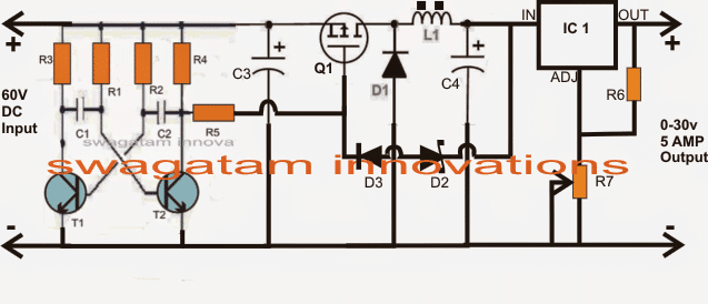
Parts List for the above 60V input, 12V, 24V output buck converter solar for the panels.
| Component | Value / Specification |
|---|---|
| Resistors | |
| R1 – R5 | 10K |
| R6 | 240 Ohms |
| R7 | 10K Potentiometer |
| Capacitors | |
| C1, C2 | 2nF |
| C3 | 100uF / 100V |
| C4 | 100uF / 50V |
| Transistors & MOSFET | |
| Q1 | Any 100V, 20A P-Channel MOSFET |
| T1, T2 | BC546 |
| Diodes | |
| D1 | Any 10A Fast Recovery Diode |
| D2 | 30V Zener, 1 Watt |
| D3 | 1N4007 |
| Inductor | |
| L1 | 30 turns of 21 SWG super enameled copper wire wound over a 10mm dia ferrite rod |
How Building the 60V to 12V/24V Buck Converter
So here we are making a DC-DC buck converter which will take 60V DC (or lower, between 40V to 60V) and bring it down to any required lower voltage. This is done using a transistor-based oscillator, a MOSFET switching stage, an inductor-based buck section, and finally, a linear voltage regulator for precise voltage control.
Step 1: Parts You Need
Main Components
BJTs → T1, T2 → These form the AMV (Astable Multivibrator) stage. Any general-purpose NPN transistors will work (like BC547 or 2N2222).
MOSFET → Q1 → This is main switching device that converts high voltage to low voltage. A good high-voltage MOSFET like IRF540, IRF840 will work.
Inductor → L1 → This is high-current inductor that stores and releases energy to step down the voltage efficiently. Can be around 100uH to 200uH with a high current rating (10A).
Diodes → D1, D2, D3 → These are used for rectification and clamping. Schottky diodes (like MB6S or 1N5822) will be best for efficiency.
Capacitors → C1, C2, C3, C4 → These filters out noise and stabilize voltage. Use at least 1000uF for C4 to ensure smooth output.
Resistors → R1 to R7 → Used for biasing, feedback and current control. Value selection depends on circuit tuning.
IC Voltage Regulator → IC1 (LM396 or LM338) → This takes the stepped-down voltage and fine-tunes it to a fixed 12V, 18V, or 24V output.
Step 2: Understanding the Circuit Sections
Now let us go deep and see how each section is working inside this circuit.
- Oscillator (Astable Multivibrator - AMV) Section
This part is made using T1, T2, along with R1, R2, R3, R4, and C1, C2.
What happens here? Well these transistors switch ON and OFF alternately, generating a high-frequency pulse (20kHz - 50kHz).
The frequency depends on R1, R2, C1, C2, and we can adjust it by tweaking these values.
The output of this AMV stage is fed to the MOSFET Q1.
- MOSFET Switching and Buck Conversion Section
The oscillating signal from the AMV is sent to Q1's gate, which makes it switch ON and OFF rapidly.
This fast switching action allows current to pass through L1 and D1, creating a step-down voltage across C4.
D2 clamps the voltage to a maximum of 30V making sure that it does not go beyond that.
- Voltage Regulation and Final Output
The bucked voltage (maximum 30V) from C4 is now sent to the LM396 voltage regulator (IC1).
IC1 adjusts this voltage to a fixed 12V, 18V, or 24V, depending on how R6 and R7 are set.
R6, R7 act as voltage dividers to set the desired output voltage.
Finally the output is stable, can deliver up to 5A and can be used for battery charging or powering DC loads.
Step 3: Assembly Instructions
- Solder the AMV circuit first
- Connect T1, T2, R1, R2, R3, R4, C1, C2 properly.
- Make sure the transistors are placed correctly (check emitter, base, collector).
- Add the MOSFET and buck components
- Place Q1 properly with the drain connected to L1 and source to ground.
- Connect D1 in parallel with L1 (cathode to L1).
- Attach D2 and D3 to clamp the voltage.
- Solder the capacitors
- C3 near Q1’s gate to stabilize switching.
- C4 at the output for filtering.
- Connect the voltage regulator IC1
- Attach IN pin to bucked voltage from C4.
- Connect OUT pin to final output.
- Adjust R6 and R7 to get desired voltage.
- Final Testing and Usage
- Apply 60V DC Input → Power the circuit and check the voltage across C4 (should be ≤ 30 V).
- Check MOSFET Switching → Measure the gate pulses to confirm oscillation.
- Check Final Output → Adjust R6/R7 to get 12V, 18V, or 24V.
- Test with Load → Attach a battery or 12V/24V device and ensure stable operation.
Conclusion
Ok so here, what we did was, we built a simple fully transistorized buck converter using basic BJTs, a MOSFET, an inductor, and a voltage regulator. This circuit can handle high voltage (40V-60V) and give us clean, regulated low voltage (12V, 18V, or 24V) with up to 5A current.
It is efficient, compact and useful for battery charging or running DC devices. If then we need higher current we can upgrade IC1 or use a better heatsink.
That is all!
Leave a Reply