• Skip to main content
  • Skip to primary sidebar

Making Easy Circuits

Learn and build electronic circuits

You are here: Home / Protection Circuits / How to Make a Testing an MOV (Metal Oxide Varistor) Surge Protector Device

How to Make a Testing an MOV (Metal Oxide Varistor) Surge Protector Device

Last Updated on February 17, 2018 by Admin Leave a Comment

The post talks about a set up for assessment and utilizing MOVs which can be special devices stipulated for consuming immediate high surge currents that could mistakenly happen in our mains electrical lines.

tvs2Bdiode2Bsurge2Bprotector
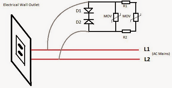
An MOV will have to be linked across LINE and NEUTRAL and not LINE and GROUND, so ground might not be essential to MOVs, essentially it basically ought to be linked across the load mains input terminals.
An MOV is made to protect against immediate high voltage surges which could survive for not more than a few nano seconds....for instance if there's an quick voltage spike of say 600 V for 3 nano seconds, the MOV will gladly counteract it by brief circuiting it across the associated terminals.
In spite of this if this type of spike maintains even for a second it could result in the MOV to get damaged and catch fire.
To establish and show the operating these particular devices you might need a 600 V AC source resulting by upgrading the domestic 220 V by means of an auto transformer, thereby making the circuit set up as demonstrated in the diagram.

mov2Btest2Bset2Bup2Bcircuit
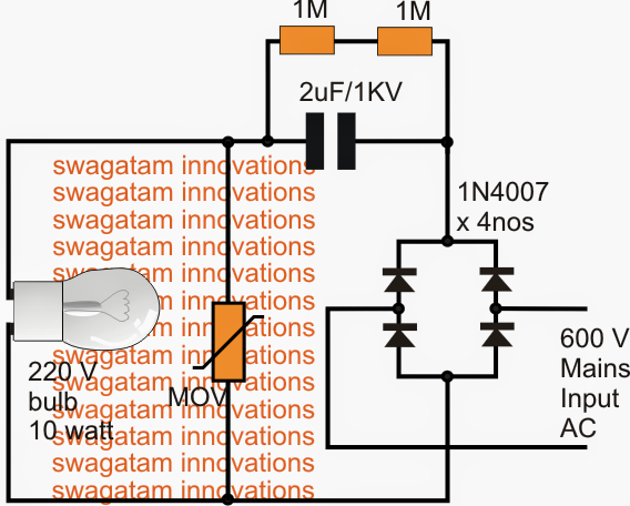
The figure exhibits a bridge network which rectifies the 600 V AC to 700 V DC and this DC is then fired across the MOV circuit carrying a susceptible 220 V, 10 watt lamp. This is achieved by way of a 2uF/1KV capacitor to be able to safeguard the MOV as it's not built to manage continual high surges.
Generally the hooked up lamp would certainly immediately get burnt when exposed to this substantial 700 V, but the experiment will hopefully demonstrate how the enormous voltage is effectively assimilated and neutralized by the MOV preserving the bulb's life.
The diode set up is not advised, simply because TVS diodes can behave like short circuit if they occur to get ruined, this could indicate the wires catching fire or the fuses blowing of.
An NTC may be chosen according to its highest voltage rating specifications, this voltage rating will figure out how much immediate high voltage the device is rated to limit.

You'll also like:

  • 1.  Gas Sensor Circuit
  • 2.  How To Make a Mains Over Load Protector Circuit for Lathe Machine
  • 3.  Simple Burglar Deterrent Circuit
  • 4.  How Decoupling in Logic Circuits Work
  • 5.  Amplifier/Loudspeaker Overload Protector Circuit
  • 6.  Simple Mains Overload Protection Circuit

About Admin

Hey friends, Thanks a bunch for stopping by this site! I am an engineer with a Bachelor of Engineering in Electronics and Telecommunication. One of my passions is gathering information from all sorts of electronics books and tutorials. I then take that information and compile it into a language that is super easy to understand. My goal is to make those complex electronics circuit concepts and technical terms much more accessible for all the new and budding electronics engineers out there. I can also design customized circuit diagrams as required by the users.
If you have any questions related to this field, please do not hesitate to drop a comment! I am always here and ready to help you out with any queries you might have. I cannot wait to hear from you!

Reader Interactions

Leave a Reply Cancel reply

Your email address will not be published. Required fields are marked *

Primary Sidebar

Categories

  • 3 Phase (4)
  • 8051 Microcontroller (1)
  • Arduino (11)
  • Audio and Amplifier (102)
  • Automation (8)
  • Battery Chargers (64)
  • Bicycle Projects (4)
  • Car and Motorcycle Projects (39)
  • Datasheets (10)
  • DIY Projects (5)
  • Electrical (15)
  • Free Energy (6)
  • Games Projects (2)
  • High Voltage (14)
  • Hobby Projects (30)
  • Household Circuits (2)
  • IC 555 Circuits (4)
  • Ignition Circuits (2)
  • Indicators (50)
  • Infrared (6)
  • Inverter Circuits (29)
  • Lights and Lamps (97)
  • Medical (8)
  • Meter and Tester Circuits (38)
  • Motor Driver (17)
  • New Circuits (56)
  • Oscillators (30)
  • Pets and Pests (5)
  • Power supply (81)
  • Protection Circuits (25)
  • PWM (8)
  • Remote Control (20)
  • Security and Alarm Circuit (48)
  • Sensors and Detectors (66)
  • Signal Processor (23)
  • Solar Controller Circuits (61)
  • SSR (3)
  • Temperature Controller (20)
  • Timer (25)
  • Transformerless (7)
  • Transmitters (12)
  • Tutorials (45)
  • UPS (2)
  • Voltage Regulators (57)
  • Water Sensor and Controller (29)
  • Home
  • Privacy Policy
  • Contact
  • Disclaimer
  • Copyright

© 2025 · Making Easy Circuits