• Skip to main content
  • Skip to primary sidebar

Making Easy Circuits

Learn and build electronic circuits

You are here: Home / Meter and Tester Circuits / Transistor Gain Tester Circuit

Transistor Gain Tester Circuit

Last Updated on April 14, 2020 by Admin Leave a Comment

You may have come across many ordinary transistor gain tester circuits designs, but this specific circuit will help you to determine the gain of high frequency RF transistors quickly with some quick potentiometer adjustments.

Circuit Working

The gain of a transistor under high frequency will depend on the DC bias factors through which it functions. This is because the optimum gain is obtained at just one specific level of collector current.
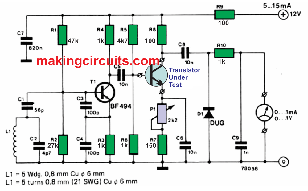
This simple transistor gain circuit as shown above was created to find out the best collector current for a given NPN RF transistor.

The transistor which is being analyzed is introduced directly into an amplifier stage that is applied with a fixed amplitude of 100 MHz signal through an oscillator stage configured around T1.

This particular oscillator signal is amplified by the transistor under test, rectified by D1 and filtered by R1O and C9 to provide a DC signal relative to the RF signal output of the transistor under test.

This, subsequently, will be proportional to the current gain of the transistor being tested. The collector current from the test transistor could be tweaked from 1 mA and 10 mA through preset P1, that must be installed with a linearly calibrated scale having these specified values.

Once this is done it is a easy job to fine-tune P1 until the optimum output voltage is received over the meter, where upon the most effective collector current could be measured directly from the P1 calibrated scale dial.

You'll also like:

  • 1.  Universal LED Bar Graph Indicator Circuit
  • 2.  Vehicle Speedometer Circuit for Precise Speed Measurements
  • 3.  Noise Level Meter Circuit
  • 4.  Accurate Analogue Frequency Meter Circuit
  • 5.  Simple Workbench Multimeter Circuit
  • 6.  Sound Decibel Meter Circuit

About Admin

Hey friends, Thanks a bunch for stopping by this site! I am an engineer with a Bachelor of Engineering in Electronics and Telecommunication. One of my passions is gathering information from all sorts of electronics books and tutorials. I then take that information and compile it into a language that is super easy to understand. My goal is to make those complex electronics circuit concepts and technical terms much more accessible for all the new and budding electronics engineers out there. I can also design customized circuit diagrams as required by the users.
If you have any questions related to this field, please do not hesitate to drop a comment! I am always here and ready to help you out with any queries you might have. I cannot wait to hear from you!

Reader Interactions

Leave a Reply Cancel reply

Your email address will not be published. Required fields are marked *

Primary Sidebar

Categories

  • 3 Phase (4)
  • 8051 Microcontroller (1)
  • Arduino (11)
  • Audio and Amplifier (102)
  • Automation (8)
  • Battery Chargers (64)
  • Bicycle Projects (4)
  • Car and Motorcycle Projects (39)
  • Datasheets (10)
  • DIY Projects (5)
  • Electrical (15)
  • Free Energy (6)
  • Games Projects (2)
  • High Voltage (14)
  • Hobby Projects (30)
  • Household Circuits (2)
  • IC 555 Circuits (4)
  • Ignition Circuits (2)
  • Indicators (50)
  • Infrared (6)
  • Inverter Circuits (29)
  • Lights and Lamps (97)
  • Medical (8)
  • Meter and Tester Circuits (38)
  • Motor Driver (17)
  • New Circuits (56)
  • Oscillators (30)
  • Pets and Pests (5)
  • Power supply (81)
  • Protection Circuits (25)
  • PWM (8)
  • Remote Control (20)
  • Security and Alarm Circuit (48)
  • Sensors and Detectors (66)
  • Signal Processor (23)
  • Solar Controller Circuits (61)
  • SSR (3)
  • Temperature Controller (20)
  • Timer (25)
  • Transformerless (7)
  • Transmitters (12)
  • Tutorials (45)
  • UPS (2)
  • Voltage Regulators (57)
  • Water Sensor and Controller (29)
  • Home
  • Privacy Policy
  • Contact
  • Disclaimer
  • Copyright

© 2025 · Making Easy Circuits