The basic dry run protection circuits using BJTs shown here provide simple ways to check for low water levels in an underground tank but without needing to use probes inside the tank. So this clever method helps prevent the motor from running when there is no water. Then the circuit includes a device that manages overflow when the water level gets too high.
We received a question on this topic from a reader of this blog asking us for advice.
Practical Considerations
Since moving the wiring from the underground tank to the motor can be a lot of work, so have you thought about checking for a dry run motor by looking at the water flow from the overhead tank instead of the underground one?
If there is no water coming into the tank then the motor should be turned off. But since it takes at least five seconds for water to reach the tank entrance the motor should not be switched off right away.
If the motor is not pumping water then it is important to turn it off. We know this could happen if the water level in the underground tank is too low or if the pump is not working properly.
I would rather not have any wiring from the underground tank to the circuit. So I want to keep an eye on the water flow at the entrance of the overhead tank. I hope I have made my request clear.
I want to control the motor by hand. So since it takes a few seconds for the water to flow into the tank if we replace the buzzer with a relay the motor will shut off automatically right after it starts.
To avoid this problem we need to give the tank some time to detect the water coming in. But I am not sure how to set up a delay. Can you help us with that?

Design No. 1
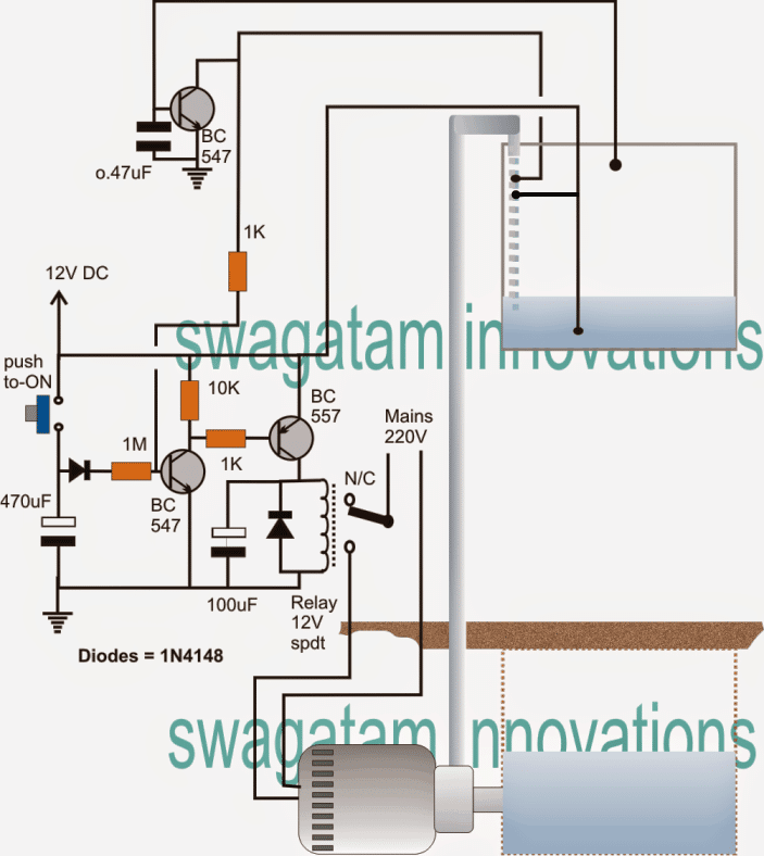
The following information can help you to understand how the circuit for the underground water pump motor dry run protector works:
A 12V AC/DC adapter powers the entire circuit.
When you press the push button for a short time, then it activates the BC547 transistor and the BC557 relay driver stage.
After you let go of the push button, then the relay driver stage stays active for a set period because of the time delay created by the 470uF capacitor and the 1M resistor.
You can adjust the delay time by changing the values of the 470uF capacitor or the 1M resistor.
When the relay is turned on then motor starts running and begins to draw water from the tank above.
The positive underwater probe connects to the probe at the mouth of the pipe as soon as the water in the overhead tank reaches the remaining water. This allows the voltage from the bottom of the probe to travel through the water and the 1K resistor to the base of the BC547 transistor.
This action locks the relay driver stage, keeping the relay active even after the time delay is over.
The motor will only stop in two specific condition.
1) When the water level in the overhead tank goes above the overflow point, then positive voltage from the lower probe connects to the probe that goes to the base of the higher BC547 transistor. This turns on the higher BC547, which then turns off the relay driver stage and stops the motor.
2) If the water in the underground tank runs out, then relay driver latch will release, and the water flow in the pipe to the overhead tank will definitely stop.
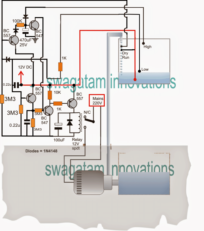
Here is an automatic version of the sump motor controller that includes a system to prevent dry running.

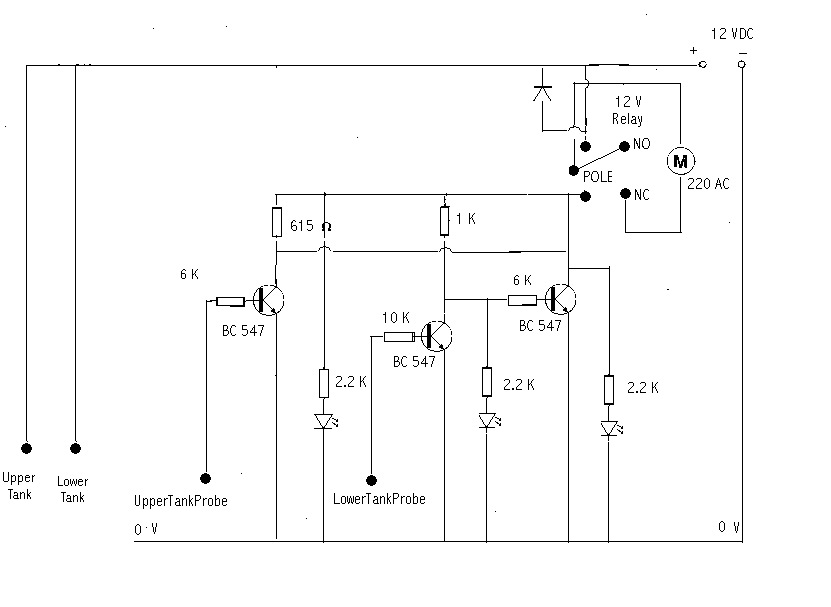
Here is another straightforward motor dry run protector that uses only BJTs.
This is a simple idea for an overflow controller circuit that can help prevent water overflow and stop the pump motor from running dry.
Mr. Lemor asked for this idea.
Technical Specifications
I found your website while looking for timer circuits, and I was amazed at what one person can accomplish!
I am referring to your article from Friday 20, 2012.
I have a similar issue. I created a circuit that seems to work on a breadboard. But I want the pump to start only when the upper tank needs water and the lower tank has enough water. Additionally if the water level in the lower tank drops too low while the pump is running then it should stop.
I am trying to figure out how to meet this last requirement.
I want to start this circuit manually, and when the pumping stops, then it should also cancel my start action. This will halt the entire process of filling the upper tank. So I think using two relays (outside the circuit) for the ON/OFF part of the project might work, but I haven’t figured it out yet.
The drawing above should illustrate what I am trying to achieve. The project/circuit is powered by an external source. The output from the circuit which is used to stop the pump, should disconnect the external source that was activated manually.
I hope you don’t mind me reaching out to share my problem. If you think it’s worth discussing then feel free to post it on your blog.
I am attaching the circuit I designed.

The Design
I want to thank Mr. Lemor for his hard work but the design above might have some issues for several reasons.
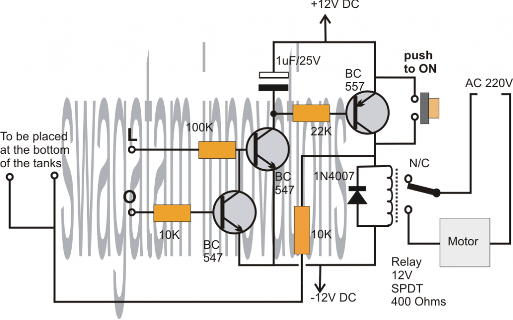
You can see the right version below (just click to make it bigger) so I will explain how the circuit works with these points:

The point L is set at a specific location inside the lower tank which helps us determine the minimum water level where the motor can operate safely.
The terminal O is located at the highest point of the upper tank where the motor needs to stop filling the tank.
The main switch to turn the motor on is controlled by a central NPN transistor that connects to point L. The switch to turn the motor off is managed by a lower NPN transistor linked to point O.
But these actions can only start when the water has a positive voltage supplied to it.
A push button switch is added to allow for a manual start when needed.
When the push button is pressed briefly then it sends a positive voltage into the tank water through the button's contacts.
If the water level in the lower tank is above point L then this voltage travels to the base of the central transistor through the water causing it to turn on.
This activation of the central transistor powers the relay driver and the motor and it keeps the relay driver transistor active so even if the push button is now released the motor continues to run.
In this active state the motor will stop under two circumstances only. If the water level drops below point L or if the water fills the upper tank to point O.
In the first case the voltage from the relay driver collector can not reach point L which breaks the latch and stops the motor.
In the second case the lower BC547 transistor activates and breaks the latch by grounding the base of the central transistor.
The overhead water level controller circuit will only work when the water level is at or above point "L" or below point "O." Also it can only start up when the push button is pressed.
Leave a Reply