In this article, we will see a universal capacitive discharge ignition or the CDI unit for any motor-assisted bicycles (motorcycles) or even the mopeds.
Ignition Without CDI
In small motor bikes without a CDI the fuel consumption can rise substantially; that is from 118 mpg at 75% throttle to 71 mpg at full throttle. The higher-than-normal fuel consumption, the higher the associated with the misfiring of the ignition. The theory can be validated by checking the spark plug and exhaust after a few rounds.
The ignition begins to skip sparks when the 30 cc two-stroke engine works at full capacity and top speed. The constructor employed this method intending to manufacture an electronic speed limiter to make sure the moped can be legally driven.
But the carburettor is unrestricted, and it conveniently supplies the fuel that results as an unburnt element in the exhaust. On top of contributing to the negative impact on fuel consumption, it damages the exhaust too.
Over time, there will be excessive carbon residue build up in the exhaust which eventually leads to complete replacement of the component.
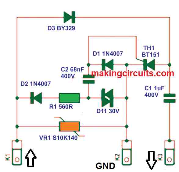
Another alternative is to dismantle the existing CDI (Capacitive Discharge Ignition) unit and alter the connections. However, it is difficult to do so because the unit is housed in a potting compound. So, we looked for what was needed to generate the sparks without restricting the speed. The result is shown in the circuit schematic.
Because the ignition coil and pickup coil are attached adjacent to the engine’s flywheel, we only need to focus on the electronics that builds the capacitor discharge into a coil at just the right moment.
The input is attached to a pickup coil that sends a single pulse for every turn of the flywheel. The output is coupled to the ignition could that delivers the high voltage pulse to the spark plug. Then, the electrical energy gets stored in Capacitor C1 through D3.
Once there is a pulse at the input, the thyristor gets activated into conduction. This action pulls C1 to ground where it can discharge to the ignition coil.
PCB Design
A one-side PCB was developed for this universal motorcycle CDI circuit, but you may notice the components are attached on both sides of the board. This was crucial because the circuit has to be kept about the same size as the existing CDI unit; 59 x 38 x 24 mm. If you review the picture of the prototype, this is clearer.

In sequence, place D1, D2 and DI1 and C2 on to the component side. Then, you must solder diode D3 and thyristor TH1 into place.
The legs of the components must be slightly bent to ensure they are on the same level as the board.
This will also make D3 ending above D2 and T1 on top of D1 and DI4. You will need to mount the MKP capacitor (C1) alongside the board while varistor (VR1) and resistor (R1) must be fitted on the solder side of the board. All three spade terminals must be soldered onto the board in the end.
Casing Details
For the casing, you can grab a small box from any electrical store, or you can build your own using acrylic.
Once the board is fully furnished with the components and connected, you can examine if the ignition generates any spark. If the spark plugs flicker correctly you may transfer the circuit into the casing and fill it with potting compound.
This step is fundamental to ensure the circuit is protected from highly possible vibration from the ignition.
Types of CDI
There are two distinct types of CDI unit in use. The first one is made by Motoplat (red) and the other is manufactured by Prueflex (blue). In both scenarios, the earth is linked to the middle connector of the CDI unit.
In the event you accidentally connect the input and output reversely, the CDI unit will not generate a spark. If this happens at all, the easiest step is to swap the red and blue wires.
Enhanced Efficiency
After the simple motor cycle CDI circuit was constructed and tested, its high efficiency effect was instantly recognizable. The engine operates much better at peak throttle and does not misfire anymore.
There is also a considerable improvement in terms of fuel consumption where the average value is now 166 mpg. Considering the mechanical limitations like the carburettor, exhaust, compression ratio etc, the top speed will not jump a huge margin.
Our experiment shows there was a rise of 2 to 2.5 mph. Overall, the biggest rewards are smoother engine operation and enhanced fuel consumption.
Good morning. I was wondering but would this circuit be good (fitting 2 of them) in a 1996 virago xv750?
And: where does the pickup connect and where is the power supply that powers the coils?
Yes, I am confused too. Where is the 100V alternator input?
I got this circuit from an old magazine.
In the circuit diagram we only see the input K1 of the pulses- pickup coil- from the flywheel system.
The supply voltage from the ignition coil that is connected?
I think K1 is supposed to be connected to the 200V AC from alternator. Pickup coil triggering is not required. The alternator AC does both triggering and high voltage supply
my bike is atala green 50cc ( YOM italay 1998-1999 ) and still could not find a suitable cdi uni for it can you help me to ged a solution for it can i know if the ignition circuit you have suggested is suitable ?
You can find the CDI circuit in homemade-circuits-projects website.
Hi , I would like to build a very simple 12 volts DC CDI (capacitive discharge ignition) If there is any diagram please help, thanks
Hi, you can try implementing the above concept…
hi where can i get the pcb for this
Universal Motorcycle CDI Circuit [Capacitor Discharge Ignition] or is there a file that i have to download to get it printed.
Hi, sorry PCB is not available online, you may have to contact a professional PCB maker