• Skip to main content
  • Skip to primary sidebar

Making Easy Circuits

Learn and build electronic circuits

You are here: Home / Power supply / Constant Voltage Transformerless Power Supply Circuit

Constant Voltage Transformerless Power Supply Circuit

Last Updated on December 26, 2024 by Admin Leave a Comment

This article transforms a basic capacitive power supply into a safer and more versatile design. The resulting transformerless circuit will offer:

  • Surge protection for handling unexpected voltage spikes.
  • Constant Stabilized voltage output for consistent power delivery.
  • Optional variable voltage for adjusting power to different devices (if needed).

This improved design will be suitable for powering a wider variety of electronic loads and circuits.

The idea was requested by Mr. David.

Technical Specifications

I remember mentioning the transformerless circuits on your blog a while back. I'm glad they worked out for me. I'm currently running a couple powering 20W and 30W LEDs!

Now, I'm working on a project with a controller, fan, and LEDs, and I need a dual power supply for it. Here's what I'm looking for:

  • Dual Outputs:
  • Output 1 (P1): 3.3-5V at 300mA (for controller)
  • Output 2 (P2): 12-40V (or higher) at 300mA (for LEDs)

The challenge is getting the 3.3V output from your Circuit without adding another capacitor. I was thinking about a couple of options:

  1. Adding a separate circuit to the first circuit's output to generate the 3.3V supply.
  2. Placing a second triac and bridge rectifier in parallel with the first one, after the capacitor, to get the lower 3.3-5V output.

Any help you can offer on the best approach for this project would be greatly appreciated!

Thanks,

The Circuit

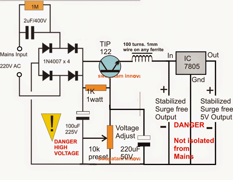
The various components work together in stages to achieve a controlled output voltage. Here's how they work:

The four 1N4007 diodes convert AC mains voltage to pulsating DC. A 10uF/400V capacitor smooths this pulsating DC.

A voltage divider circuit with a TIP122 transistor (MJE13005 for better safety) reduces the high voltage (around 310V) to the desired output level. You can adjust the output voltage (e.g., 12V) with a 10K potentiometer.

To prevent the transistor from turning on during initial switch-on and avoid surge damage, a 220uF/50V capacitor is used. The inductor also helps limit the inrush current during startup.

For a precise 5V output or other desired voltage levels, a 7805 voltage regulator can be added.

Circuit Diagram

5 V regulated transformerless power supply circuit diagram

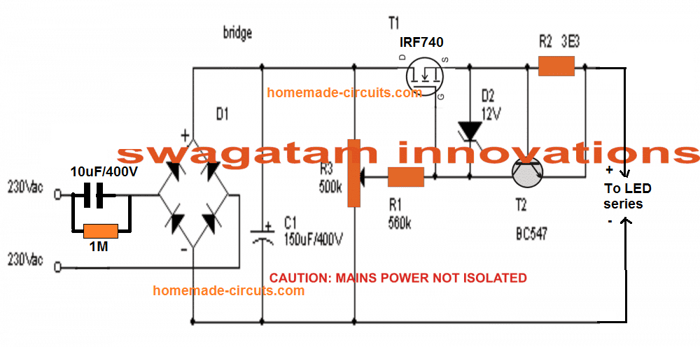
Upgrade with MOSFET Control:

This emitter follower circuit can be improved by using a MOSFET source follower power supply. This new design also includes an additional current control stage using a BC547 transistor.

The complete circuit diagram for this upgraded version is shown below:

MOSFET controlled transformerless power supply circuit diagram

You'll also like:

  • 1.  Simple Variable Power Supply Circuit for Benchwork
  • 2.  Designing a IC 723 Power Supply with Variable Voltage and Current
  • 3.  How to Build a 0 to 50V, 0 to10amp Variable Dual Power Supply Circuit
  • 4.  How to Calculate SMPS Transformer
  • 5.  Transformerless Power Supply for LED String Lights
  • 6.  5V, 12V Buck Converter Circuit SMPS 220V

About Admin

Hey friends, Thanks a bunch for stopping by this site! I am an engineer with a Bachelor of Engineering in Electronics and Telecommunication. One of my passions is gathering information from all sorts of electronics books and tutorials. I then take that information and compile it into a language that is super easy to understand. My goal is to make those complex electronics circuit concepts and technical terms much more accessible for all the new and budding electronics engineers out there. I can also design customized circuit diagrams as required by the users.
If you have any questions related to this field, please do not hesitate to drop a comment! I am always here and ready to help you out with any queries you might have. I cannot wait to hear from you!

Reader Interactions

Leave a Reply Cancel reply

Your email address will not be published. Required fields are marked *

Primary Sidebar

Categories

  • 3 Phase (4)
  • 8051 Microcontroller (1)
  • Arduino (11)
  • Audio and Amplifier (102)
  • Automation (8)
  • Battery Chargers (64)
  • Bicycle Projects (4)
  • Car and Motorcycle Projects (39)
  • Datasheets (10)
  • DIY Projects (5)
  • Electrical (15)
  • Free Energy (6)
  • Games Projects (2)
  • High Voltage (14)
  • Hobby Projects (30)
  • Household Circuits (2)
  • IC 555 Circuits (4)
  • Ignition Circuits (2)
  • Indicators (50)
  • Infrared (6)
  • Inverter Circuits (29)
  • Lights and Lamps (97)
  • Medical (8)
  • Meter and Tester Circuits (38)
  • Motor Driver (17)
  • New Circuits (56)
  • Oscillators (30)
  • Pets and Pests (5)
  • Power supply (81)
  • Protection Circuits (25)
  • PWM (8)
  • Remote Control (20)
  • Security and Alarm Circuit (48)
  • Sensors and Detectors (66)
  • Signal Processor (23)
  • Solar Controller Circuits (61)
  • SSR (3)
  • Temperature Controller (20)
  • Timer (25)
  • Transformerless (7)
  • Transmitters (12)
  • Tutorials (45)
  • UPS (2)
  • Voltage Regulators (57)
  • Water Sensor and Controller (29)
  • Home
  • Privacy Policy
  • Contact
  • Disclaimer
  • Copyright

© 2025 · Making Easy Circuits