The explained IC 555 based Automatic water level control circuit is a straightforward approach, project.
It could automatically switch ON and OFF of the domestic water pump set based on the water level of the tank.
You are able to utilize this motor driver circuit at your home or college employing more affordable components.
The rough cost of the project is around $ 5 only. The principal good thing about this water level controller circuit is that it automatically controls the water pump with no involvement of the consumer.
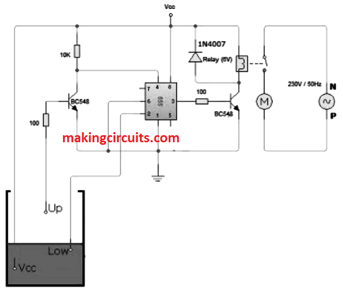
The control stage of the circuit is an NE 555 IC; here we have manipulated the flip-flop within chip 555.
Our project include two water level sensors, one particular attached at the top and the other towards the bottom.
Functioning of this circuit is practically identical to a stable mutlivibrator Bi.
Working simulation of this circuit is additionally provided below. Undoubtedly this can help you make your academic project.
How this Automatic Water Tank Level Controller Work
-We understand that the property of the chip 555, ie its output will increase once the voltage at the second pin (trigger pin) is no more than 1/3 VDC.
We may also reset the IC by making use of a low voltage to the 4th pinout (reset pins).
In this particular project you will find 3 wires immersed in the water tank. We will specify two levels-Low Water Level (Low) and High (Up) Level. One of the pins of the probe or is of Vcc.
The lower level sensor is hooked up to the trigger (2) of the pin 555 CI. Therefore, the voltage at the 2nd pin is Vcc while it is inside water.
When the water level reduces, the second probe is detached from the water voltage, and the trigger pin gets to be under Vcc. Then the output of 555 gets high.
The output 555 is placed on a BC548 transistor, it triggers the relay coil and also the water pump collectively are switched on.
When the water level goes up, the upper level probe is included in water and the transistor turns OFF. Its collector voltage is VCE (sat) = 0.2.
The low voltage on the 4th pinout resets the IC. Therefore, the output of 555 turns into 0V. Thus the motor is switched OFF.
For a basic demo of this project, you may use a DC motor directly connected across the output of the 555 and ground rather than relay.
For practical execution, you have to make use of a relay. Relay rating is preferred based on the load (motor). Relay 32 amp is most effective for household purposes.
List of Electronic components:
-Power supply (6v)
-NE chip 555
- Resistors (100Ωx2, 10k)
-Relais (6V, 30A)
-BC 548 transistor x2
-1N4007 Diode
Hello, can I use this circuit on a 12 volt power supply?
Yes 12 V can be used, in that case the relay should be also 12 V rated.
its a wrong circuit, when the water level goes up from empty, first it touches the ‘low’ probe and the gets IC turned off from here, and it will not work until the ‘high’ probe.
please help me with this issue
It is a correct circuit, just one thing is missing in the circuit. Connect a 330K or 470K from pin#2 to ground. As soon as the water level goes below the low level the motor will start, and when the water rises to the high level, the motor will stop.
I am an electronics novice. I would like to make a water level controller to be able to empty a below ground sump when the water level is high and to shut off the pump when the water level is low. I have a 240v submersible pump which pumps about 200l per minute. I have had endless trouble with float setups so would like to have a floatless setup. Can you help with plans and/or instructions?
It’s good.
Now I would like to know that whether the device is available with two inputs i.e., one is borewell and the other is sump delivering to two different tanks.
Will the same circuit work in 12 volt?
yes it will work
Thanks for your response.
This is not the same circuit I suppose.
Because in case I have a lower tank, feed by the bomb (pump), and in case there is no water, the bomb should not start avoiding crush the bomb (pump).
I think that the circuit should be different but I dont know how… because in case in lower tank there is no water, there is no connection between VCC and LOW from the circuit.
Does this circuit with a 1000 lts tank? or 2000 lts tank?
Thanks in advance
Alejandro From Buenos Aires Argentina
You are welcome.
The above circuit can be applied for your requirement.
For the lower tank you must use the same circuit which is shown above.
for the upper tank also use another similar circuit but do not use “LOW” probe, use only the “Up” probe for the upper tank, so that it activates only for the overflow condition.
Now you can put the contacts of the two relays in series along with the motor and mains.
check which contacts of the relay remains connected when the lower tank has more than “low” level water and the upper tank has lower than the “Up” level. use these contacts in series.
Use Vcc for the both the tanks from a 12V AC source this will allow the system to work even with 1000 liter tank
Excellent ! thanks ! and how is the circuit if you have a tank below to feed the water pump… ?
One tank above and other above !
Thanks, you will need two such circuits to control the pump separately using two relays for the two tanks