• Skip to main content
  • Skip to primary sidebar

Making Easy Circuits

Learn and build electronic circuits

You are here: Home / Sensors and Detectors / Zero Crossing Detector Circuit

Zero Crossing Detector Circuit

Last Updated on November 17, 2024 by Admin Leave a Comment

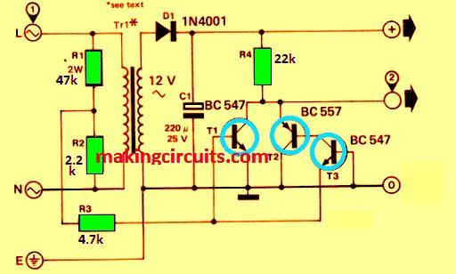
Many complex circuits and integrated circuits contain zero crossing detectors, but we will deal only with the detector here. The detector produces a pulse each time the mains voltage goes through zero potential.
zero crossing detector

The circuit created is quite easy. It takes the mains voltage, rectifies it via D1, smooths it through C1 and produces a direct voltage of 17 V.

A portion of the mains voltage taken from across R2 operates the transistors T1-T3.

T1 continues to work while T2 and T3 switch off when the voltage is positive, while the reverse happens when the voltage is positive, ie, T1 turns off and T2 and T3 conduct.

None of the transistors work when the voltage lies between +0.6 V and -0.6 V.

A short positive pulse is obtained as a result of the high output voltage produced due to this. There is no phase shift due to the isolating transformer since the circuit is driven directly by the mains.

If you are going to supply the direct voltage output to any external circuit, make sure the current is within the permissible limit of the circuit and also the TR1 transformer rating.

You may also have to increase the value of C1. Similarly, always keep in mind that this and any connected external circuits are supplied directly from the mains.

Waveform of zero crossing output pulse

waveform

You'll also like:

  • 1.  12V to 24V Voltage Doubler Circuit using IC 4093
  • 2.  High Power Triac Dimmer Circuit for 1000 watt Loads
  • 3.  Red, Green Signal Lamp Flasher Circuit for Railways
  • 4.  LM317 Dispaly Intensity Controller Circuit
  • 5.  220V Touch Dimmer Switch Circuit with 4 Step Control
  • 6.  110V, 220V Voltage Regulator Circuit

About Admin

Hey friends, Thanks a bunch for stopping by this site! I am an engineer with a Bachelor of Engineering in Electronics and Telecommunication. One of my passions is gathering information from all sorts of electronics books and tutorials. I then take that information and compile it into a language that is super easy to understand. My goal is to make those complex electronics circuit concepts and technical terms much more accessible for all the new and budding electronics engineers out there. I can also design customized circuit diagrams as required by the users.
If you have any questions related to this field, please do not hesitate to drop a comment! I am always here and ready to help you out with any queries you might have. I cannot wait to hear from you!

Reader Interactions

Leave a Reply Cancel reply

Your email address will not be published. Required fields are marked *

Primary Sidebar

Categories

  • 3 Phase (4)
  • 8051 Microcontroller (1)
  • Arduino (11)
  • Audio and Amplifier (102)
  • Automation (8)
  • Battery Chargers (64)
  • Bicycle Projects (4)
  • Car and Motorcycle Projects (39)
  • Datasheets (10)
  • DIY Projects (5)
  • Electrical (15)
  • Free Energy (6)
  • Games Projects (2)
  • High Voltage (14)
  • Hobby Projects (30)
  • Household Circuits (2)
  • IC 555 Circuits (4)
  • Ignition Circuits (2)
  • Indicators (50)
  • Infrared (6)
  • Inverter Circuits (29)
  • Lights and Lamps (97)
  • Medical (8)
  • Meter and Tester Circuits (38)
  • Motor Driver (17)
  • New Circuits (56)
  • Oscillators (30)
  • Pets and Pests (5)
  • Power supply (81)
  • Protection Circuits (25)
  • PWM (8)
  • Remote Control (20)
  • Security and Alarm Circuit (48)
  • Sensors and Detectors (66)
  • Signal Processor (23)
  • Solar Controller Circuits (61)
  • SSR (3)
  • Temperature Controller (20)
  • Timer (25)
  • Transformerless (7)
  • Transmitters (12)
  • Tutorials (45)
  • UPS (2)
  • Voltage Regulators (57)
  • Water Sensor and Controller (29)
  • Home
  • Privacy Policy
  • Contact
  • Disclaimer
  • Copyright

© 2025 · Making Easy Circuits