• Skip to main content
  • Skip to primary sidebar

Making Easy Circuits

Learn and build electronic circuits

You are here: Home / Indicators / 3 in 1 Circuit Fault Tester Circuit

3 in 1 Circuit Fault Tester Circuit

Last Updated on January 11, 2021 by Admin Leave a Comment

The 3 in 1 tester circuit explained in the following article is actually a combination of signal injector, signal tracer, and logic probe, which allows the user to accurately test and troubleshoot any electronic circuit or circuit PCB fault, quickly.

How the Circuit Works

This 3-in-1 circuit fault tester circuit is developed around a 4049-hex inverter/buffer. In figure below, you can spot two inverters (from a 6-inverter unit) which are used in a dual-frequency signal-injector circuit.

3 in 1 tester circuit compressed

Another inverter is utilized as a logic problem and the rest of them are assigned as a sensitive dual-input, audio signal tracer.

Signal Injector

The signal-injector section of the 3-in-1 set comprises of gates U1-a and U1-b. These gates are set as a two-frequency, pulse-generator circuit.

Normally, the generator’s output frequency is about 10 kHz. However, once S2 is closed, there is a drop and the signal become close to 100 Hz.

For higher frequencies, you must bring down the values of C1 and C2. Inversely, you have o increase the capacitor values to obtain lower frequencies. For this circuit, both AC and DC outputs are supplied.

Logic Probe

The logic-probe section of the circuit consists of U1-c and a few LEDs which function to indicate the “high” or “low” state by switching on an LED. Once a logic high is supplied to the input of U1-c, the output of the inverter switches to low.

This low output reverse biases LED2 so it stays off. At the same time, the low output from U1-c forward biases LED1 which causes it to turn on.

However, when a logic low is set at U1-c’s input the whole situation converses, where LED2 becomes lit and LED1 turns off. Resistors R2 and R3 constrict the flow of current from the LEDs to around 10 mA.

Signal Tracer

The audio-signal tracer portion of this circuit consists of U1’s three remaining inverters (U1-d to U1-f) which are set ad linear audio-amplifier that is utilised to enhance the input signal by a factor of 10 or 100.

The boosted output signal supplies a miniature piezo element for sound detection.

Parts List
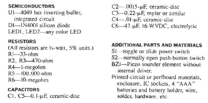
3 in 1 tester circuit parts list compressed

The total cost for this 3 in 1 tester circuit parts is very cheap (less than five dollars). Furthermore, you can effortlessly construct it on a perfboard or PCB, depending on your choice.

What is most important is keeping the leads short and a tidy circuit schematic.

You'll also like:

  • 1.  Test Logic with this Logic Probe Circuit
  • 2.  Simple Crystal Tester Circuit
  • 3.  Simple Temperature Indicator using BC547 Transistor
  • 4.  Loudspeaker Power Indicator Circuit
  • 5.  Transistorized Music Level Indicator Circuits for Amplifiers
  • 6.  Easily Create the Most Basic Temperature Indicator Circuit

About Admin

Hey friends, Thanks a bunch for stopping by this site! I am an engineer with a Bachelor of Engineering in Electronics and Telecommunication. One of my passions is gathering information from all sorts of electronics books and tutorials. I then take that information and compile it into a language that is super easy to understand. My goal is to make those complex electronics circuit concepts and technical terms much more accessible for all the new and budding electronics engineers out there. I can also design customized circuit diagrams as required by the users.
If you have any questions related to this field, please do not hesitate to drop a comment! I am always here and ready to help you out with any queries you might have. I cannot wait to hear from you!

Reader Interactions

Leave a Reply Cancel reply

Your email address will not be published. Required fields are marked *

Primary Sidebar

Categories

  • 3 Phase (4)
  • 8051 Microcontroller (1)
  • Arduino (11)
  • Audio and Amplifier (102)
  • Automation (8)
  • Battery Chargers (64)
  • Bicycle Projects (4)
  • Car and Motorcycle Projects (39)
  • Datasheets (10)
  • DIY Projects (5)
  • Electrical (15)
  • Free Energy (6)
  • Games Projects (2)
  • High Voltage (14)
  • Hobby Projects (30)
  • Household Circuits (2)
  • IC 555 Circuits (5)
  • Ignition Circuits (2)
  • Indicators (50)
  • Infrared (6)
  • Inverter Circuits (29)
  • Lights and Lamps (97)
  • Medical (8)
  • Meter and Tester Circuits (38)
  • Motor Driver (17)
  • New Circuits (56)
  • Oscillators (30)
  • Pets and Pests (5)
  • Power supply (80)
  • Protection Circuits (25)
  • PWM (9)
  • Remote Control (20)
  • Security and Alarm Circuit (48)
  • Sensors and Detectors (66)
  • Signal Processor (23)
  • Solar Controller Circuits (62)
  • SSR (3)
  • Temperature Controller (20)
  • Timer (25)
  • Transformerless (7)
  • Transmitters (12)
  • Tutorials (45)
  • UPS (2)
  • Voltage Regulators (57)
  • Water Sensor and Controller (29)
  • Home
  • Privacy Policy
  • Contact
  • Disclaimer
  • Copyright

© 2025 · Making Easy Circuits