• Skip to main content
  • Skip to primary sidebar

Making Easy Circuits

Learn and build electronic circuits

You are here: Home / Lights and Lamps / Simple High Power LED Flashlight Circuit

Simple High Power LED Flashlight Circuit

Last Updated on January 10, 2018 by Admin Leave a Comment

Making a high power LED flashlight circuit is simple. All you need is to gather the components and follow instruction to build the system.

This article has explained in detail [along with diagrams] the procedure to make a LED Flashlight:

Recommended Components

  • 24 Super-bright LEDs
  • 3 batteries [AA]
  • Resistor to manage current flow

Procedure of Assembly

 led flashlight circuit

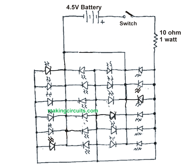
Fig 1.0: The circuit design shows the basic layout of the design.


Referring to the circuit diagram, all the 24 LEDs are attached together in parallel form. While the optimum voltage to generate bright light from the LEDs need 3.3 – 4 volt [Current – 20mA], but here the current use is 0.4 – 0.6A.

The circuit used in this demonstration is a 3 x AA 1.2 V along with nickel-metal hydride battery. A 1ohm resistor is used to limit the current supply to ensure the voltage remain 3.6V.

However, the assembly of the resistor and the LED is made on a PCB Board. Once the things are in place the next step is to solder the 1ohm resistor and the LED and further soldering other parts on the PCB.

The next and final part is to attach the PCB to the battery holder. You can use glue in this case.

If you are planning to use this high power LED flashlight circuit on steel-made cabinet or cars, you need to add a magnetic system.

You'll also like:

  • 1.  How to Build a Automatic Fish Aquarium Light Optimizer Circuit
  • 2.  220V Transformerless LED Driver Circuit
  • 3.  4 Watt LED Driver Circuit Using IC LM338
  • 4.  Make this Police Strobe Light Circuit
  • 5.  Building a 100-Watt LED Driver with Current Regulation
  • 6.  Simple String Light Circuits for Festival Decorations

About Admin

Hey friends, Thanks a bunch for stopping by this site! I am an engineer with a Bachelor of Engineering in Electronics and Telecommunication. One of my passions is gathering information from all sorts of electronics books and tutorials. I then take that information and compile it into a language that is super easy to understand. My goal is to make those complex electronics circuit concepts and technical terms much more accessible for all the new and budding electronics engineers out there. I can also design customized circuit diagrams as required by the users.
If you have any questions related to this field, please do not hesitate to drop a comment! I am always here and ready to help you out with any queries you might have. I cannot wait to hear from you!

Reader Interactions

Leave a Reply Cancel reply

Your email address will not be published. Required fields are marked *

Primary Sidebar

Categories

  • 3 Phase (4)
  • 8051 Microcontroller (1)
  • Arduino (11)
  • Audio and Amplifier (102)
  • Automation (8)
  • Battery Chargers (64)
  • Bicycle Projects (4)
  • Car and Motorcycle Projects (39)
  • Datasheets (10)
  • DIY Projects (5)
  • Electrical (15)
  • Free Energy (6)
  • Games Projects (2)
  • High Voltage (14)
  • Hobby Projects (30)
  • Household Circuits (2)
  • IC 555 Circuits (5)
  • Ignition Circuits (2)
  • Indicators (50)
  • Infrared (6)
  • Inverter Circuits (29)
  • Lights and Lamps (97)
  • Medical (8)
  • Meter and Tester Circuits (38)
  • Motor Driver (17)
  • New Circuits (56)
  • Oscillators (30)
  • Pets and Pests (5)
  • Power supply (80)
  • Protection Circuits (25)
  • PWM (9)
  • Remote Control (20)
  • Security and Alarm Circuit (48)
  • Sensors and Detectors (66)
  • Signal Processor (23)
  • Solar Controller Circuits (62)
  • SSR (3)
  • Temperature Controller (20)
  • Timer (25)
  • Transformerless (7)
  • Transmitters (12)
  • Tutorials (45)
  • UPS (2)
  • Voltage Regulators (57)
  • Water Sensor and Controller (29)
  • Home
  • Privacy Policy
  • Contact
  • Disclaimer
  • Copyright

© 2025 · Making Easy Circuits