Building an automatic light for washroom is not at all complex. All you need to do is to follow the steps as described in this report to get the derived result. Using an automatic switch would help to save electricity. Moreover, the system is designed in a way to run on lesser power, thereby saving your pocket!
Consider a situation – you enter into the washroom and the light turns on automatically; as you move out the light turns off! Yes, we are talking about an automatic switching solution for the washroom. With this solution you don’t have to worry to keep check on the washroom light, which we often forget to switch off at times.
How it works
The operational procedure of this effective device is simple. When one steps into the washroom, the system automatically detects the presence and turns the light on. As soon as the person leaves the washroom, the system again detects the absence and turns the light off.
How to build the proposed automatic light circuit for washroom?
The following diagram in Figure details the way the circuit is built:
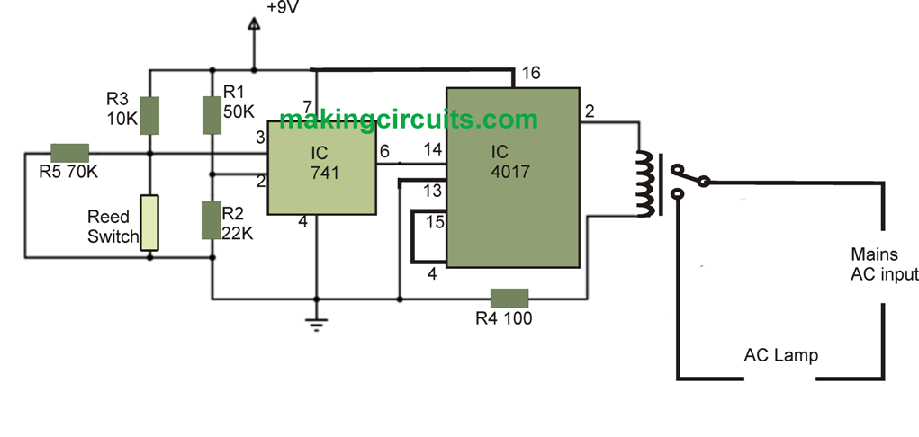
The primary component that you need to develop the system is the reed switch. This switch comes in two type, and we will use the one that shuts-off in normal state and turns on with the effect of magnetic field. 9V power supply is applied to the circuit – Pin-16 of 4017 IC has 9V and Pin-8 is left on ground state.
As a comparator, the circuit uses op-amp IC 741 and is defined in such a way to maintain high output state when the washroom door remains closed. The automatic washroom light circuit is further strategically placed onto the door so that it can come close to the reed switch when the door closes. Furthermore, the IC 4017 is deployed in a way to act on both instance – door open or close. So, the next time when the washroom door is opened and closed, the circuit cuts the relay making the light to extinguish. While IC 4017 is designed to handle nine counts, here we have applied only two counts and then reset. Because of the IC’s capacity to manage count value, here we have used it as one-bit counter.
As the washroom door opens, the reed switch initiates and the output of the IC 741’s sixth pin goes high, and as the door closes Pin-6 goes off. Again when the washroom door is closed, this enable triggering of the decade counter of IC 4017, and thus the relay helps toggling the system in ON and OFF state every time the door is opened or closed.
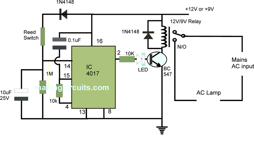
Improved Corrected Version of the above described automatic washroom light circuit
As you may note that the above explained design is full of flaws, it was taken from another site and it seems that the designer of the circuit has no knowledge of electronics.
First of all a IC 741 is not required for the reed switch operation in response to the door closing or opening.
Secondly, the relay should not be connected directly to 4017 output, must be done through a transistor driver.
Third, the output from IC 4017 must be taken from pin#2, and not from pin#3.
Fourth, pin#15 must be configured with a resistor/capacitor network as shown in the below corrected version:
thank you! very much……for helping me
you are welcome!!
Can we solder relay to pcb?
Will it shot?
you can, but make sure the AC contact points are at least 5mm apart from each other
congrats!my circuit is working but there is a small problem of time delay[td].
circuit gives it’s output after 10 sec.
what will happen if I decrease 10uF capacitor to 2 or 5 uF capacitor because TD=R x C.
means if we decrease the capacitance td will also decrease.
Am I right? What to do?
congrats! decrease 1M to 100K
ok.thanks
then what can be the fault in my circuit,any suggestion pls..
can u send me the photo of your project plz.
because there are 10 outputs of 4017, sometimes due to voltage spike at pin#14 the logic can jump to one of the outputs which are not in use…you can try increasing the 0.1uF value to 0.33uF or any other nearby higher value, this will ensure that at power switch ON the logic sequence starts at pin#3.
then on table power the circuit with 12V DC and check the circuit response by bringing a magnet close to the reed and then removing it, repeat this as many times as you want and check whether the relay is switching ON/OFF or not….this is the procedure a circuit is supposed to be checked before installing.
if the relay does not respond, then your IC may be faulty or some other pinout connection error could be there.
ok!thanks sir….
my Ic is CD4017BE. Is that a right IC?
it is fine!!
thanks very much
i’ll try it again
hi,pls tell me something
Both the circuits are not working.I am sure with my work.
if the second circuit is not working, then 100% your circuit is at fault…
when the reed closes, it sends a positve pulse to the pin#14 which causes the output of the 4017 to change and switch ON the relay and the light.
but yes to switch OFF the light again you will have to close the door again…meaning the light will operate only when the door is being closed
Sorry,how to connect the relay with that circuit from AC main source and AC lamp,,I have to submit simulation for the circuit
the relay connections are clearly shown n the second diagram. The N/C is unused, the wiring is made across the N/O and the pole of the relay, which run in series with the load and the mains AC input points
Dear;
WHAT ABOUT FOR THE IMPROVED ONE?
you can build it, it will work for sure
how to get its simulation?
simulation for the last circuit is not required, it has been tested and verified practically by me….