The submit talks about a 200 + 200 watt wireless home theater circuit utilizing a class D amplifier and a Bluetooth headset as the wireless module.
In one of the earlier content we discovered concerning the internal elements of a Bluetooth headset gadget and in one more article we outlined how its speaker pins could be utilized for inducing a relay.
As a reaction to the above request, in this post we examine how a Bluetooth Headset would come in useful to make a home theater system circuit.
The concept is easy, it's regarding choosing an appropriate contrary power amplifier circuit and developing the Bluetooth Headset speaker wires with the inputs of the amplifier.
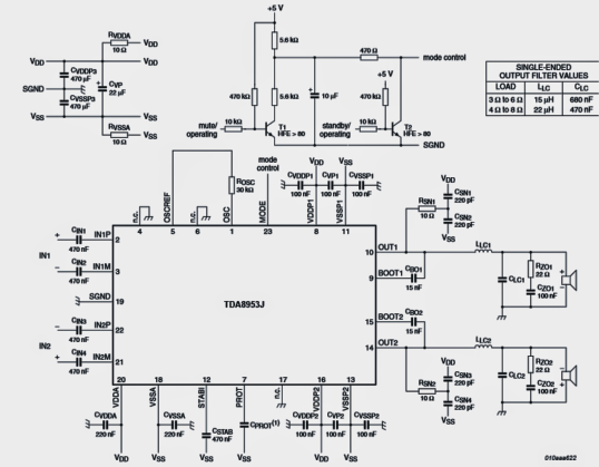
For the suggested application here we certainly have utilized an illustration 200 + 200 watt class D power amplifier circuit making use of the IC TDA8953 from NXP Semiconductors.
The entire schematic of the power amplifier may be observed in the below presented diagram. It may include two differential inputs which means the chip facilitates a stereo class D input.
The output is single finished though and is effective at driving two ground referenced 4 ohm speakers rated at 200+ watts each.
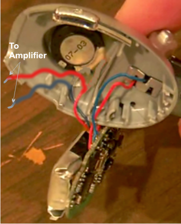
Each of the inputs of the above demonstrated class D amplifier could possibly be instantly set up with the cut/stripped speaker wires of a scavenged Bluetooth headset circuit as provided below:
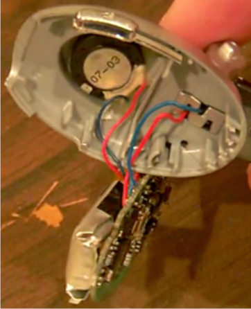
Disconnect the speaker wires from the speaker, strips the ends cautiously for the suggested integrations with the amplifier inputs
For making use of both the inputs of the amplifier and for loving a stereophonic home theater response, an additional appropriate and properly combined Bluetooth headset unit is going to be essential.
As soon as the integration of the two Headsets, combined with source Bluetooth is conducted, a throbbing magnificent class D 400 watt stereo music may very well be felt over the hooked up speakers.
The system could possibly be placed as a home theater system or simply for enjoying a pure 400 watts of music from your cell phone or other Bluetooth suitable gadgets.
For those who already have a ready made home theater amplifier system, hook up the input of the amplifier with any one cut/stripped speaker wire of the Bluetooth headset (if the amplifier is not a differential type) and make absolutely sure the negative line of the headset is created common with the amplifier negative line.
On the other hand a bridge network may very well be raised for remedying the different output from the headset speaker and the output could possibly be straight joined with the inputs of the single ended amplifier.
george says
I see so many VSS and VDD connection while at the supplying side are only 2 options, with or without 10ohm resistors. It is a bit confusing for me, there is no specification, all have notes like VSS and VDD. Which one should I use? I guess those outputs which have resistors will be connected at VSSA and VDDA. Am I right?
admin says
Join the common terminals together and connect with the + and – supplly lines respectively