• Skip to main content
  • Skip to primary sidebar

Making Easy Circuits

Learn and build electronic circuits

You are here: Home / Hobby Projects / Chirping Bird Circuit

Chirping Bird Circuit

Last Updated on December 19, 2018 by Admin 2 Comments

There are as many variations of the electronic chirping bird circuits as there are birds. And the circuits are being used for a wide range of applications, such as door bell, as horns or reverse horns in cars and scooters, and of course as bird chirps incorporated in plastic birds of a large variety.

The circuit shown here comprises two astable multivibrators the top one sets the tone of circuit and the lower one sets the rate of repetition. The two bias resistors of the tone oscillator are fed the output of rate oscillator through variable resistor VR1.

chirping bird sound simulator circuit

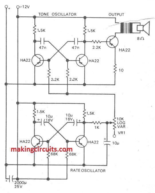
The arrangement produces a change of-tone every half cycle—the basic tone being set by the position of variable arm of VR1. With 2.2k resistors in the base and 10k variable resistor, the tone can be varied over a wide range. Change of tone is also possible with change in the collector-base coupling capacitors of tone oscillator.

The repetition rate can be varied by changing the collector-base coupling capacitors. The l0uF capacitor from the variable point of the potentiometer to ground shapes the square wave generated by the rate oscillator.

While the square wave applied to the base resistors of the tone oscillator would result in sharp tonal changes, introduction of capacitor round off the square wave produces a sort of warbling effect. Change of the supply voltage also affects the tone, but it can be reset by adjusting the variable resistor. Smooth operation is possible over a wide range of supply voltages.

Thus, it is fairly easy to obtain identical sounds for different supply voltages such as 6V for scooters or auto-rickshaws and 12V for trucks or cars. The tone oscillator produces a square wave output fed to output transistor the loudspeaker is coupled through a transformer.

The harmonics can be eliminated by a suitable capacitor across the primary of the transformer. It is much easier to manipulate this circuit to obtain the desired sound effect compared with the blocking oscillator circuit. Further, a large value capacitor across the supply charges as the supply is switched on to the circuit and it discharges through the circuit after the supply is switched off.

Thus the sound tends to decay slowly rather than being abruptly shut off. Period of decay depends on the value of capacitor and the output from the circuit.

You'll also like:

  • 1.  Simple Light Activated Switch Circuit
  • 2.  How to Make an Opamp with Transistors (BJTs)
  • 3.  Fading Red Eye Circuit
  • 4.  Simplest Homemade Electric Guitar
  • 5.  Very Sensitive Clap Switch Circuit
  • 6.  How to make a Simple Music Box Circuit

About Admin

Hey friends, Thanks a bunch for stopping by this site! I am an engineer with a Bachelor of Engineering in Electronics and Telecommunication. One of my passions is gathering information from all sorts of electronics books and tutorials. I then take that information and compile it into a language that is super easy to understand. My goal is to make those complex electronics circuit concepts and technical terms much more accessible for all the new and budding electronics engineers out there. I can also design customized circuit diagrams as required by the users.
If you have any questions related to this field, please do not hesitate to drop a comment! I am always here and ready to help you out with any queries you might have. I cannot wait to hear from you!

Reader Interactions

Comments

  1. Shahrokh Adhami says

    May 15, 2022 at 7:12 pm

    I love your bird circuit I assemble very beautiful but still doesn’t warble and my output transistor got hot please help me thanks

    Reply
    • admin says

      May 22, 2022 at 7:31 pm

      which transistors did you use, and did you use the transformer?

      Reply

Leave a Reply Cancel reply

Your email address will not be published. Required fields are marked *

Primary Sidebar

Categories

  • 3 Phase (4)
  • 8051 Microcontroller (1)
  • Arduino (11)
  • Audio and Amplifier (102)
  • Automation (8)
  • Battery Chargers (64)
  • Bicycle Projects (4)
  • Car and Motorcycle Projects (39)
  • Datasheets (10)
  • DIY Projects (5)
  • Electrical (15)
  • Free Energy (6)
  • Games Projects (2)
  • High Voltage (14)
  • Hobby Projects (30)
  • Household Circuits (2)
  • IC 555 Circuits (5)
  • Ignition Circuits (2)
  • Indicators (50)
  • Infrared (6)
  • Inverter Circuits (29)
  • Lights and Lamps (97)
  • Medical (8)
  • Meter and Tester Circuits (38)
  • Motor Driver (17)
  • New Circuits (56)
  • Oscillators (30)
  • Pets and Pests (5)
  • Power supply (80)
  • Protection Circuits (25)
  • PWM (9)
  • Remote Control (20)
  • Security and Alarm Circuit (48)
  • Sensors and Detectors (66)
  • Signal Processor (23)
  • Solar Controller Circuits (62)
  • SSR (3)
  • Temperature Controller (20)
  • Timer (25)
  • Transformerless (7)
  • Transmitters (12)
  • Tutorials (45)
  • UPS (2)
  • Voltage Regulators (57)
  • Water Sensor and Controller (29)
  • Home
  • Privacy Policy
  • Contact
  • Disclaimer
  • Copyright

© 2025 · Making Easy Circuits