• Skip to main content
  • Skip to primary sidebar

Making Easy Circuits

Learn and build electronic circuits

You are here: Home / Timer / How to Build a Timer Circuit with Auto Pause and Resume During Power Failures

How to Build a Timer Circuit with Auto Pause and Resume During Power Failures

Last Updated on February 17, 2018 by Admin Leave a Comment

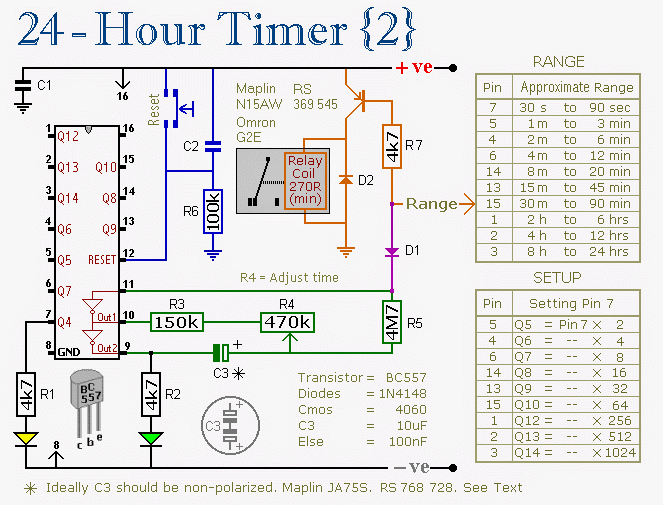
The submit describes an effective remedy which might be useful for pausing the counting technique of a timer IC throughout power problems, and also restart the method when mains is restored, being sure an continuous working of the timer.

242 1
The altered version of the above 4060 timer circuit may be observed in the following schematic. The circuit contains an automated pause and restart function of the IC's counting procedure in the course of power downfalls and restorations respectively.


pausememorytimercircuit
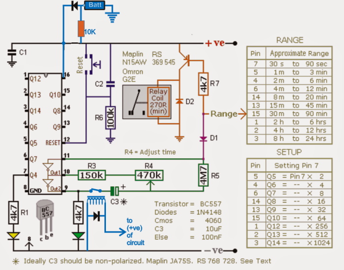
The parts that happen to be tinted in blue are the placed changes, we are able to notice a battery backup being added at pin16 of the IC via diodes, and a relay at pin9 of the IC.
Considering that the capacitor C3 is liable for beginning the counting strategy of the timer while it gets completely charged, this element might be aimed at the designed pausing/resuming of the timer.
As might be observed in the diagram, this is all simply executed by linking C3 to the "hot" pin9 of the IC via a pair of relay contacts (N/O to be precise).
Nevertheless for creating the above execution work, the IC ought to be provided with its basic running current and voltage while the mains is unavailable.
This is achieved by using a battery support to the IC via isolating diodes at pin16 of the IC.
The connected 10K resistor ensures that the battery maintains obtaining the needed trickle charge provided that the mains remains to be existing.
When power is very first turned on, the relay at pin9 triggers and links C3 in the line to ensure that the IC has the capacity to start usually and commence its counting method.
In an event of a mains malfunction,the battery requires over and sustains the IC powered in an uninterruptible way, although also at the same time the relay at pin9 of the IC disconnects C3 from the line to be able to quit the capacitor from reducing the kept immediate charge via pin9, this guarantees that the elapsed time period gets locked inside the capacitor for that specific instance until the mains is renewed.
The occasion mains power comes back C3 is associated back with the circuit by the relay, allowing it to restart the counting practice precisely from where it had quit and not from zero as it would elsewhere do if the above mods weren't integrated.
The above could possibly be also exactly the same used in other timer ICs for example in IC 555 monostable circuit or IC 4047, IC 556 IC 4022 etc.
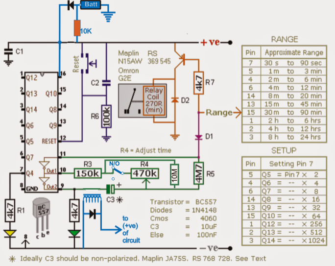
As mentioned in the feedback the above designs might have some restrictions and imperfections, an affordable set about could be noticed in the below presented diagram which might hopefully permit minimum conflict, not a lot more than 1% +/-. Notice the relay connection in blue across R4 and the inclusion of the high value 10M hold resistor.


timer2Bpower2Bmains2Bfailure2Bcorrection

You'll also like:

  • 1.  1 Hour to 5 Hour Customizable Timer Circuit
  • 2.  Bedside Lamp Timer Circuit
  • 3.  Universal Digital, Programmable Timers Circuits
  • 4.  Simple Delay ON Timer Circuit using Two BC547 Tansistors
  • 5.  Accurate 24 Hour Timer Circuit
  • 6.  Simple Dark Room Timer Circuit for Photographers

About Admin

Hey friends, Thanks a bunch for stopping by this site! I am an engineer with a Bachelor of Engineering in Electronics and Telecommunication. One of my passions is gathering information from all sorts of electronics books and tutorials. I then take that information and compile it into a language that is super easy to understand. My goal is to make those complex electronics circuit concepts and technical terms much more accessible for all the new and budding electronics engineers out there. I can also design customized circuit diagrams as required by the users.
If you have any questions related to this field, please do not hesitate to drop a comment! I am always here and ready to help you out with any queries you might have. I cannot wait to hear from you!

Reader Interactions

Leave a Reply Cancel reply

Your email address will not be published. Required fields are marked *

Primary Sidebar

Categories

  • 3 Phase (4)
  • 8051 Microcontroller (1)
  • Arduino (11)
  • Audio and Amplifier (102)
  • Automation (8)
  • Battery Chargers (64)
  • Bicycle Projects (4)
  • Car and Motorcycle Projects (39)
  • Datasheets (10)
  • DIY Projects (5)
  • Electrical (15)
  • Free Energy (6)
  • Games Projects (2)
  • High Voltage (14)
  • Hobby Projects (30)
  • Household Circuits (2)
  • IC 555 Circuits (5)
  • Ignition Circuits (2)
  • Indicators (50)
  • Infrared (6)
  • Inverter Circuits (29)
  • Lights and Lamps (97)
  • Medical (8)
  • Meter and Tester Circuits (38)
  • Motor Driver (17)
  • New Circuits (56)
  • Oscillators (30)
  • Pets and Pests (5)
  • Power supply (80)
  • Protection Circuits (25)
  • PWM (9)
  • Remote Control (20)
  • Security and Alarm Circuit (48)
  • Sensors and Detectors (66)
  • Signal Processor (23)
  • Solar Controller Circuits (62)
  • SSR (3)
  • Temperature Controller (20)
  • Timer (25)
  • Transformerless (7)
  • Transmitters (12)
  • Tutorials (45)
  • UPS (2)
  • Voltage Regulators (57)
  • Water Sensor and Controller (29)
  • Home
  • Privacy Policy
  • Contact
  • Disclaimer
  • Copyright

© 2025 · Making Easy Circuits