• Skip to main content
  • Skip to primary sidebar

Making Easy Circuits

Learn and build electronic circuits

You are here: Home / Temperature Controller / Temperature to Voltage Converter Circuit

Temperature to Voltage Converter Circuit

Last Updated on March 30, 2020 by Admin Leave a Comment

Temperature to voltage converter is a device which converts each degree rise in ambient temperature into a corresponding rise in the output voltage from the device.

It is easy to build the circuit of temperature to voltage converter having a range between 0 to 24 ˚ Celsius ranges of temperatures.

temperature to volatge converter

Main Features

The final output of the circuit of this thermometer is around 500 mV/˚C. The temperatures are readable on a Voltmeter that has degree Celsius calibration.

In building such a thermometer, a negative temperature co-efficient thermistor or NTC is used to keep the circuit simpler and more accurate. The advantage of using an NTC is that the temperature co-efficient of resistance is large enough.

However, there is the disadvantage that the temperature coefficient does not remain constant when such NTC is used.

This results in nonlinear temperature-voltage output. However, for this particular simple temperature to voltage converter, within the range of 0˚ to 24˚C the linearity is good enough.

Construction Hints

To build the converter, an op-amp IC1 has to be connected as a differential amplifier.

This amplifier gets the feed from four legged bridge consisting of four resistors, R1 to R4. The fixed arms of the circuit bridge consist of R1, R2, R3 and P1 while R4 acts as the variable arm.

In such a circuit, the voltage at the connecting point of R1 and R2 is about 3.4 Volts. The NTC is kept at 0˚ C.

How to Setup the Circuit

This is when P1 is adjusted to get a zero op-amp output when the voltage at the juncture of R3 and R4 is also 3.4 V.

As temperature rises, the NTC resistance goes down, making the voltages across its ends fall down further. This leads to an increase of op-amp output.

To make the output exactly 0.5V/˚C the R8 and R9 resistors may be adjusted. It is notable that the value of R8 and R9 should be same while doing so.

Whcin Op Amps can be Used

General purpose op-amps, such as 741, 3130, and 3140 can be used as an IC. In case of 741, no compensation capacitor is required. R4 can be built with any 10k NTC Thermistor.

However, the smaller the size, the faster are the results due to lower thermal inertia of the thermistor.

Similarly, there is no restriction of using the 5k or 15k ones, but the values of P1 and R3 must be altered in a given ratio.
You'll also like:

  • 1.  How to Make a Small Induction Cookware
  • 2.  Digital Temperature Indicator Circuit
  • 3.  Efficient Soldering Iron Station Circuits for Saving Energy
  • 4.  Thermal Indicator Circuit for Heatsinks
  • 5.  Automatic Soldering Iron Switch Circuit
  • 6.  How to Make a 220V, 25 Amp Heater Controller Circuit

About Admin

Hey friends, Thanks a bunch for stopping by this site! I am an engineer with a Bachelor of Engineering in Electronics and Telecommunication. One of my passions is gathering information from all sorts of electronics books and tutorials. I then take that information and compile it into a language that is super easy to understand. My goal is to make those complex electronics circuit concepts and technical terms much more accessible for all the new and budding electronics engineers out there. I can also design customized circuit diagrams as required by the users.
If you have any questions related to this field, please do not hesitate to drop a comment! I am always here and ready to help you out with any queries you might have. I cannot wait to hear from you!

Reader Interactions

Leave a Reply Cancel reply

Your email address will not be published. Required fields are marked *

Temperature to Voltage Converter Circuit

Last Updated on November 17, 2024 by Admin Leave a Comment

The post explains a simple temperature to voltage converter circuit using IC LM317. The idea was requested by one of the dedicated members of this blog.

Technical Specifications

I have eurotherm TS200A temperature controller.this is thyrister based.

This required 0-5V control voltage. I want one temperature control circuit when temperature is 25deg C the voltage is 0V. Temperature reduces the control voltage increase from 0-5V.

Please provide the circuit diagram.

Thank you.

The Design

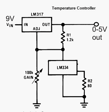
A simple layout for the proposed temperature to voltage converter circuit can be seen in the following diagram.

temperaturetovoltageconvertercircuit 1

LM334 which is a precision temperature sensor chip is configured with another precision voltage regulator IC LM317 circuit forming an accurate, linear temperature to voltage converter circuit.

The gain pot and R2 may be tweaked and experimented for achieving the desired temperature to voltage ratio.

As per the request, the voltage needs to be 0 at 25 degree C, this may be done by creating an atmosphere at the specified temperature and then adjust the pot to get a 0V at the output.

The above adjustment would hopefully allow the output to produce 1V increment for every 4.16 degree decrease in the temperature around LM334, this may also need some tweaking.

You'll also like:

  • 1.  Temperature to Voltage Converter Circuit
  • 2.  Thermal Touch Switch Circuit
  • 3.  How to Make a 220V, 25 Amp Heater Controller Circuit
  • 4.  Greenhouse Temperature and Humidity Controller Circuit
  • 5.  Automatic Ceiling Fan Circuit
  • 6.  Heatsink Temperature Monitor Circuit

About Admin

Hey friends, Thanks a bunch for stopping by this site! I am an engineer with a Bachelor of Engineering in Electronics and Telecommunication. One of my passions is gathering information from all sorts of electronics books and tutorials. I then take that information and compile it into a language that is super easy to understand. My goal is to make those complex electronics circuit concepts and technical terms much more accessible for all the new and budding electronics engineers out there. I can also design customized circuit diagrams as required by the users.
If you have any questions related to this field, please do not hesitate to drop a comment! I am always here and ready to help you out with any queries you might have. I cannot wait to hear from you!

Reader Interactions

Leave a Reply Cancel reply

Your email address will not be published. Required fields are marked *

Primary Sidebar

Categories

  • 3 Phase (4)
  • 8051 Microcontroller (1)
  • Arduino (11)
  • Audio and Amplifier (102)
  • Automation (8)
  • Battery Chargers (64)
  • Bicycle Projects (4)
  • Car and Motorcycle Projects (39)
  • Datasheets (10)
  • DIY Projects (5)
  • Electrical (15)
  • Free Energy (6)
  • Games Projects (2)
  • High Voltage (14)
  • Hobby Projects (30)
  • Household Circuits (2)
  • IC 555 Circuits (5)
  • Ignition Circuits (2)
  • Indicators (50)
  • Infrared (6)
  • Inverter Circuits (29)
  • Lights and Lamps (97)
  • Medical (8)
  • Meter and Tester Circuits (38)
  • Motor Driver (17)
  • New Circuits (56)
  • Oscillators (30)
  • Pets and Pests (5)
  • Power supply (80)
  • Protection Circuits (25)
  • PWM (9)
  • Remote Control (20)
  • Security and Alarm Circuit (48)
  • Sensors and Detectors (66)
  • Signal Processor (23)
  • Solar Controller Circuits (62)
  • SSR (3)
  • Temperature Controller (20)
  • Timer (25)
  • Transformerless (7)
  • Transmitters (12)
  • Tutorials (45)
  • UPS (2)
  • Voltage Regulators (57)
  • Water Sensor and Controller (29)
  • Home
  • Privacy Policy
  • Contact
  • Disclaimer
  • Copyright

© 2025 · Making Easy Circuits