You can make a basic device to stop your water tank from overflowing using just one IC 4049 chip. This device, not only prevents overflow but also shows you the water levels as the tank fills up.
Circuit Diagram
How the Circuit Works
When the water gets to the top of the tank, a sensor turns on a switch that starts the pump to drain the water.
The design is very straightforward. Using just one chip makes it easy to put together, set up, and look after.
The fact that the tap water we get at home conducts electricity pretty well is used to make this system work.
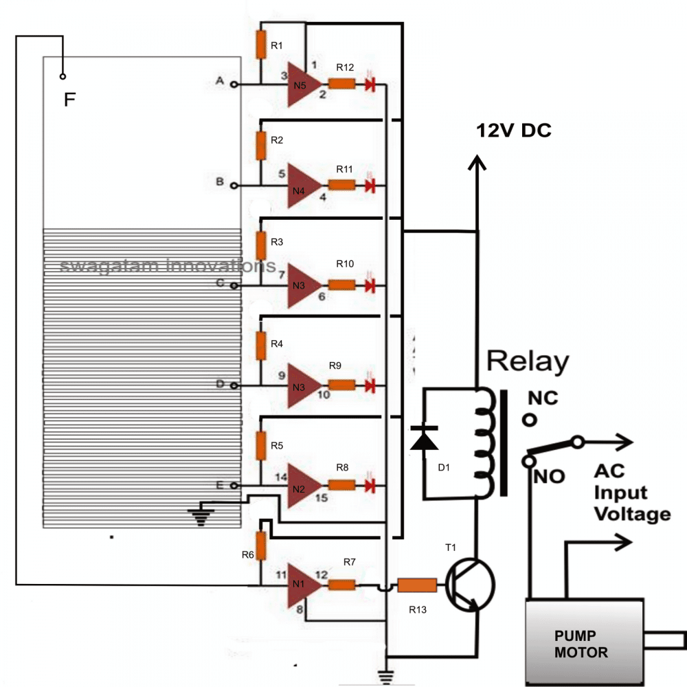
A single CMOS IC 4049 chip is used for detecting water levels and controlling the pump.
CMOS chips are great for this because they’ are sensitive and don’t need much power to work.
The six NOT gates in the IC 4049 are lined up with their inputs inside the tank to detect the water level.
The negative end of the power source is at the bottom of the tank, so it touches the water first.
This means the sensors inside the tank touch the negative end one by one as the water level rises.
NOT gates flip the input signal, so if the input is negative, the output will be positive.
So, when the water touches the NOT gate inputs, their outputs switch to positive, turning on the LEDs that show the water level.
All the gate inputs are connected to the positive end through a big resistor.
This keeps the LEDs off when the tank is empty because the gate inputs start high, making their outputs low.
The last gate controls the pump and is set at the top of the tank.
When the water touches this gate’s input, it turns on a transistor that powers the pump through a relay.
The pump starts and moves the water out of the tank.
This stops the tank from overflowing, and the LEDs give a real-time update of the water level.
Parts List
- R1 to R6 = 2M2,
- R7 to R12 = 1K,
- All LEDs = Red 5mm,
- D1 = 1N4148,
- Relay = 12 V, SPDT,
- T1 = BC547B
- N1 to N5 = IC 4049
Each sensor point consists of standard brass screw terminals mounted on a plastic rod at the specified measured intervals, connected to the circuit via flexible, insulated conducting wires (14/36 gauge).
Adding a Relay to the above Circuit
The circuit we talked about seems to have a big problem. The way it’s set up, the relay might keep turning the motor on and off over and over again as soon as the water gets too high and then again when it drops just a little below the highest sensor.
People probably wont like this.
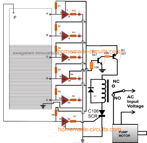
You can fix this issue by adding an SCR and a transistor to the circuit, like in the diagram that follows:
How the Circuit Works
- The smart change makes sure the motor starts as soon as the water hits the “F” mark, and it keeps working to pump out water even if the level falls below “F”… until it gets lower than the “D” mark.
- At first when the water gets higher than the “D” mark, the two transistors turn on, but a switch called a relay cant turn on yet because the SCR, is off at that time.
- As the tank fills up and the water reaches the “F” mark, NOT gate N1 activates, which turns on the SCR. This, in turn, starts the relay and the motor.
- The water pump starts to remove water from the tank, which slowly empties it. Even when the water goes below the “F” mark, the pump doesnt stop because the SCR stays on.
- The pump continues to work, making the water level keep going down until it’s below the “D” mark.
- As soon as this happens, the transistors turn off, cutting off power to the relay, which then turns off the SCR and the motor. Everything goes back to how it was at the start.
Leave a Reply