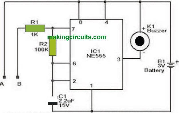
In this article we talk about an easy water level alarm circuit using a 555 timer designed to generate an audible alarm as soon as the water level reaches a predetermined stage. The circuit could be powered through a 3V battery and is extremely hassle-free to work with.
The circuit is dependent on an astable multivibrator wired close to IC1 (NE 555). The working frequency of the astable multivibrator will here rely on the capacitor C1, the resistors R1, R2 and also the resistance via the probes A and B.
When there is no water across the sensor probes, these are going to be open and as a result the Multivibrator is not going to generate oscillations and the buzzer is not going to sound.
If you have water around the probes, a current will probably stream via the water, the circuit is going to be closed to some degree and the IC will start to generate oscillations with a frequency relative to the value C1, R1, R2 and also the resistance of the water in the probes.
The buzzer produces an audible tune indicating the existence of water within the sensing probes.

Notes:
The above IC 555 water level alarm circuit can be powered through a 3V battery.
Build the circuit over a good quality PCB or a strip board.
The probes may possibly is made up of a couple of insulated aluminum copper wires.
You can put probes at the level where an individual must diagnose the exact level.
Using IC 555 Astable
Water-activated alarms, such as Rain Alarms and Cistern Alarms are pretty simple to build and use. In these alarms, tap water and rain water is used instead of pure water for detecting the presence of water. The reason behind this is that water that has impurity acts reasonably well as conductor of electricity.
Circuit Description
The idea behind creating this Water level Alarm is to switch ON an alarm tone when water is detected by the circuit. Here, an IC 555 astable produces the alarm sound. Although pin 4 of the IC 555 astable can be used in the water alarm, it is not utilized.

Here, the circuit is powered by a small 9 Volt battery which is pretty low for use extensively and cost-effectively. Therefore, the astable is switched on and off utilizing the pin 4 of the circuit.
As it is possible to connect the sensor to produce the desired effect , the result is always uncertain. Lack of water makes it impossible to start the oscillator. So, the system does not work effectively.
The supply of water is therefore provided to the oscillator by means of Tr1. The Tr1 is kept in emitter follower mode and always kept in the positive supply rail. Tr1 is cut off when there is no supply of water.
Tr1 usually have too low voltage to create the oscillation and it is in no way suitable to work alongside a small 9 Volt battery.
When there is enough water to provide Tr1 a high gain, the oscillator gets the full supply of Voltage. There is a switch S1 to stop/start the Alarm whenever necessary.
Construction
The most notable point of construction of a Water Activated Alarm is that, one needs to construct a water sensor. It, however, is not too difficult to make a water sensor.
For example, any water-attached two copper strips can start the unit to operate. There are many other ways to construct the sensor. Printed Circuit Boards are a good alternative. Even gluing some copper wires on an insulated material with small distance from one another can work good enough.

Leave a Reply