• Skip to main content
  • Skip to primary sidebar

Making Easy Circuits

Learn and build electronic circuits

You are here: Home / Audio and Amplifier / Guitar Swell Pedal Circuit

Guitar Swell Pedal Circuit

Last Updated on April 7, 2020 by Admin Leave a Comment

Swell pedals are the mechanical pedals used by guitarists to control the volume using their foot since their hands would be tied up during a performance.

This equipment is usually built into electronic organs along with the other pedals.

Guitarists swear by the swell pedal to allow them control over the measured combination of vocals and music.

How it Works

guitar swell pedal

A swell pedal is an extremely easy circuit by itself, consisting of a potentiometer that is controlled using a foot pedal through a toothed bar. But the mechanical construction is a far more complicated job, which the present circuit intends to bypass.

The circuit is built into a flat case about the size of the user’s shoe, as shown in figure below. A hollowed piece of foam rubber in the shape of a wedge with a cropped head is attached to the lid of the case.

swell pedal assembly

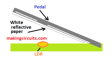
The LED D5 and an LDR or light-dependent resistor, sticks out from the lid. The top of the foam rubber is then glued with a small metal or plastic sheet whose underside is covered by a white paper or cardboard. A small rubber mat is then attached on top of the sheet.

When the musician presses the foam rubber down, the reflective white paper or cardboard comes closer to the LED and LDR, resulting in the LDR resistance decreasing.

The amplification, inversion and compensation of IC1 causes a voltage across IC2, which, in turn, controls the drive current that transistor T1 provides to the OTA or operational transconductance amplifier IC3.

How to Calibrate

Assemble the swell pedal box to seal the electro-optical circuit in a light-proof environment. Then calibrate P1 to bring the sound level to the desired point when the pedal is not operated.

Pressing down on the pedal will increase the sound level as required. P1 should be attached outside the pedal box to allow easy adjustment for different circumstances.

You'll also like:

  • 1.  250 Watt MOSFET Power Amplifier Circuit
  • 2.  How To Make a Digital Voice Changer Circuit
  • 3.  FET Amplifier Circuits
  • 4.  Simple Radio Circuit
  • 5.  30 Watt Stereo Amplifier Circuit Using IC TDA1521
  • 6.  Very Low Frequency (VLF) Converter Circuit

About Admin

Hey friends, Thanks a bunch for stopping by this site! I am an engineer with a Bachelor of Engineering in Electronics and Telecommunication. One of my passions is gathering information from all sorts of electronics books and tutorials. I then take that information and compile it into a language that is super easy to understand. My goal is to make those complex electronics circuit concepts and technical terms much more accessible for all the new and budding electronics engineers out there. I can also design customized circuit diagrams as required by the users.
If you have any questions related to this field, please do not hesitate to drop a comment! I am always here and ready to help you out with any queries you might have. I cannot wait to hear from you!

Reader Interactions

Leave a Reply Cancel reply

Your email address will not be published. Required fields are marked *

Primary Sidebar

Categories

  • 3 Phase (4)
  • 8051 Microcontroller (1)
  • Arduino (11)
  • Audio and Amplifier (102)
  • Automation (8)
  • Battery Chargers (64)
  • Bicycle Projects (4)
  • Car and Motorcycle Projects (39)
  • Datasheets (10)
  • DIY Projects (5)
  • Electrical (15)
  • Free Energy (6)
  • Games Projects (2)
  • High Voltage (14)
  • Hobby Projects (30)
  • Household Circuits (2)
  • IC 555 Circuits (5)
  • Ignition Circuits (2)
  • Indicators (50)
  • Infrared (6)
  • Inverter Circuits (29)
  • Lights and Lamps (97)
  • Medical (8)
  • Meter and Tester Circuits (38)
  • Motor Driver (17)
  • New Circuits (56)
  • Oscillators (30)
  • Pets and Pests (5)
  • Power supply (80)
  • Protection Circuits (25)
  • PWM (9)
  • Remote Control (20)
  • Security and Alarm Circuit (48)
  • Sensors and Detectors (66)
  • Signal Processor (23)
  • Solar Controller Circuits (62)
  • SSR (3)
  • Temperature Controller (20)
  • Timer (25)
  • Transformerless (7)
  • Transmitters (12)
  • Tutorials (45)
  • UPS (2)
  • Voltage Regulators (57)
  • Water Sensor and Controller (29)
  • Home
  • Privacy Policy
  • Contact
  • Disclaimer
  • Copyright

© 2025 · Making Easy Circuits