Now we explain one powerful voltage regulator circuit using one single chip IC called LM196 which can give big 10 amp current and can give variable voltage from around 1.
25V to 15V DC or even more if we want then.
About that IC LM196 or also called LM396
This IC LM196 is actually one full in one chip device which we can use for building strong voltage regulator circuits.
It is like high power high performance regulator IC that we can set for giving any voltage between 1.
25V to 15V.
But that is not only thing so it can also push more than 10 amp current without getting tired.
So now if we are someone who is always doing projects where we need clean regulated voltage and that also with big amps then this one chip can solve all those problems easily.
That means we do not have to use big heavy transistor regulators or complex stuff so we can just take this one IC and build our own heavy duty power supply for personal or professional use however we like.
Earlier we have seen in many posts that we used LM338 so yeah that one is also same type adjustable voltage regulator but that one cannot go above 5 amps then.
So it is OK for medium jobs but not for heavy loads.
But now with this LM196 or LM396 we do not have that 5 amp limit then.
This one can give full 10 amp and even more so it wins here and we can use it for more tough jobs also.
Main Features of LM196 Adjustable Regulator IC
Let us now look at all that important specifications this IC gives us.
Output voltage can be fixed or adjusted very precisely with only around plus minus 0.
8V error or less.
We can set voltage as low as 1.
25V and go up to 15V DC without problem.
It will always give 10 amp current or more then this is guaranteed
It is verified and tested under something called P plus product enhancement testing so means tough testing passed.
Even when it is fully loaded the power it will waste as heat will not go beyond 70 watts.
It has inside protection so if we short circuit the output or overload it then it will protect itself.
Also it cannot burn from heat then it will shut down safely when too hot and restart when cool.
Even if something bad happens like the adjustment pin gets disconnected then still it will keep output safe so this is also guaranteed.
One Important Note
The company says it will give 1.
25V to 15V output but wait there is more to this.
If we want then we can go above 15V also but only one condition we must not cross the input output voltage difference of 20V then.
So if we want to take say 25V at the output then we must give minimum 45V at the input.
That is because the difference should stay under 20V max then.
This is given in the datasheet and we can use this trick to get even higher voltages from this same IC then.
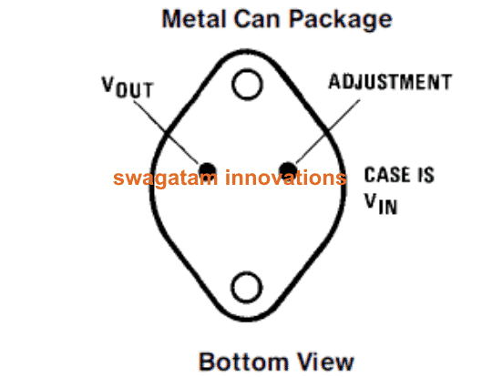
LM196 Pinout Details
Now we explain how to identify those pins of this IC.
If we keep the metal tab facing downwards and the flat side of the body towards us then.
The right side pin is the Adjustment Pin so we use this one to set the output voltage.
The left side pin is the Output Pin so this is where our regulated voltage comes out.
The big metal case or body is the Input so this is where we give our raw DC voltage in.
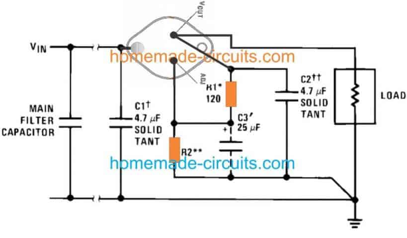
10 amp power supply circuit application
Now we explain that 10 amp power supply circuit which is built using this IC called LM196 or LM396.
This is that standard basic circuit for getting 10 amp regulated voltage and in this we are using our LM196 IC which we just discussed in previous part.
We can see the full diagram below and we will now understand how this works step by step.
How this circuit works and what we must take care of
Now we can see the circuit looks very simple and clean.
That is because this IC is already designed to do all the work inside it.
So we only need to put correct parts outside and it will work properly.
That resistor R2 which we see is used for adjusting the output voltage.
If we turn that then we can change the voltage level at the output as per our requirement
This setting is actually same like what we do for LM338 or LM317.
So if anyone has already worked with those, then this part will look familiar
But now since this one is giving 10 amp big current then we must take care of some wiring rules also.
All Grounds Must Be Common and Properly Connected.
We must connect all the ground wires and pins in this circuit to one single common ground.
If we do not do that then some parts will start working wrongly or we will see wrong voltage at output.
This common ground should be the main negative rail which is coming out from the bridge rectifier.
That bridge rectifier is not shown here but it will be there before the IC.
And the positive output wire must be connected from the correct output pin of the IC directly and taken to the load.
Why we must take care of Ground and Positive Wiring
Since this circuit is working with 10 amps of current, that much current is not like small signal level.
So when current flows in a wire then that wire itself gives some resistance to that current.
That resistance creates voltage drop if the current is high.
So that means the longer the wire or the thinner the wire, the more voltage will drop across it.
So now if we use long wires or PCB tracks for the positive and ground, then even if our IC is giving correct voltage, we may see lower voltage at the load.
That is why we must use thick and short wires for ground and positive connections and directly take them from the IC to the load.
If we do this properly then we can get full 10 amp regulated voltage from this power supply without problem.
Leave a Reply