• Skip to main content
  • Skip to primary sidebar

Making Easy Circuits

Learn and build electronic circuits

You are here: Home / Power supply / 4.5 V, 6 V, 9 V , 12 V Power Supply Circuit

4.5 V, 6 V, 9 V , 12 V Power Supply Circuit

Last Updated on June 21, 2020 by Admin 2 Comments

THIS little power supply supplies a range of switch selectable output controlled voltages from 4.5 to 12 volts, selectable by a switch.

The supply provides up to 400 mA and the output can stand up to a short circuit with no destruction. Hence , it is well suited for the experimenter or for use with high drain appliances.

FIG1 1

How it works

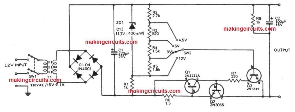
The 120V line voltage is decreased to 15 volts by transformer T1, and this secondary voltage can now be fullwave rectified by rectifier bridge D1 D4.

The bridge rectifier output is filtered by C1 to deliver somewhere around 20 volts dc. The series combination, of Zener diode ZD1 fed by resistor R1, supplies a stabilized voltage of about 13 volts which can be used along the voltage divider R2, R3, R4 and R5.

Hence a series of reference voltages 4.5 V, 6 V, 9 V , 12 V are created for the regulator, in which the positive rail is set and the negative rail is the one which is adjusted.

Transistor Q3 is an emitter follower in which the output (emitter) is around 0.6 V higher (more positive) compared to base. The base voltage is determined by SW2 from one of the tappings on the reference voltage divider.

Due to the fact Q3 are not able to manage the specified output current, it makes Q2, a power transistor, which could handle the necessary load.

Once the load surpasses 400 mA (around), the voltage decrease around R6 forward biases Q1 which usually activates and shunts current away from the base of Q2.

Therefore the regulator seems to lose control and the output voltage drops, restricting the current to 400 mA. As the power dissipated in Q2 in case of short circuit conditions is about 10 watts, Q2 needs to be fitted to a heatsink.

Furthermore, resistor R7 limits the current provided by Q3 to a safe value (for Q3) under short circuit conditions. If a fully variable supply is needed, a 10 k potentiometer needs to be employed instead of the voltage divider. The potentiometer wiper is subsequently fed straight to the Q3 base.

You'll also like:

  • 1.  High Current Transformerless Power Supply Circuit
  • 2.  How to Calculate SMPS Transformer
  • 3.  220V to 12V SMPS Transformerless Power Supply Circuit
  • 4.  3.3V 2amp SMPS Circuit for LEDs
  • 5.  Simple 0.6V to 12V Boost Converter Circuit
  • 6.  Make this 15V 10 Amp Voltage Regulator Circuit Using IC LM196

About Admin

Hey friends, Thanks a bunch for stopping by this site! I am an engineer with a Bachelor of Engineering in Electronics and Telecommunication. One of my passions is gathering information from all sorts of electronics books and tutorials. I then take that information and compile it into a language that is super easy to understand. My goal is to make those complex electronics circuit concepts and technical terms much more accessible for all the new and budding electronics engineers out there. I can also design customized circuit diagrams as required by the users.
If you have any questions related to this field, please do not hesitate to drop a comment! I am always here and ready to help you out with any queries you might have. I cannot wait to hear from you!

Reader Interactions

Comments

  1. Alexandra says

    April 17, 2021 at 2:36 pm

    May I know what are materials to use?

    Reply
    • admin says

      April 18, 2021 at 9:00 pm

      Please check the circuit diagram, all the parts numbers are provided there

      Reply

Leave a Reply Cancel reply

Your email address will not be published. Required fields are marked *

Primary Sidebar

Categories

  • 3 Phase (4)
  • 8051 Microcontroller (1)
  • Arduino (11)
  • Audio and Amplifier (102)
  • Automation (8)
  • Battery Chargers (64)
  • Bicycle Projects (4)
  • Car and Motorcycle Projects (39)
  • Datasheets (10)
  • DIY Projects (5)
  • Electrical (15)
  • Free Energy (6)
  • Games Projects (2)
  • High Voltage (14)
  • Hobby Projects (30)
  • Household Circuits (2)
  • IC 555 Circuits (4)
  • Ignition Circuits (2)
  • Indicators (50)
  • Infrared (6)
  • Inverter Circuits (29)
  • Lights and Lamps (97)
  • Medical (8)
  • Meter and Tester Circuits (38)
  • Motor Driver (17)
  • New Circuits (56)
  • Oscillators (30)
  • Pets and Pests (5)
  • Power supply (81)
  • Protection Circuits (25)
  • PWM (8)
  • Remote Control (20)
  • Security and Alarm Circuit (48)
  • Sensors and Detectors (66)
  • Signal Processor (23)
  • Solar Controller Circuits (61)
  • SSR (3)
  • Temperature Controller (20)
  • Timer (25)
  • Transformerless (7)
  • Transmitters (12)
  • Tutorials (45)
  • UPS (2)
  • Voltage Regulators (57)
  • Water Sensor and Controller (29)
  • Home
  • Privacy Policy
  • Contact
  • Disclaimer
  • Copyright

© 2025 · Making Easy Circuits