The LT® 1038 is a 3 terminal regulator which is specifically designed to handle an output current of 10 A at voltage levels ranging from over 1.2 V to 32V. The IC can be obtained in a typical T0-3 power package having 3 pinouts namely Input, ADJ, Output that are plug-in compatible with other industry adjustable regulator variants, such as the LM117, LM317 and LM138, LM338.
Furthermore, the IC LT1038 is a ideal substitute for the LM396, LM196, although the latter is rated to handle only up to a maximum voltage of 15 V.
Besides outstanding load and line regulations, the LT1038 is internally protected with features like current limiting, safe area protection and thermal shutdown.
Innovative current limiting circuitry makes it possible for transient load currents up to 24 A to be accessible for 500 µs such that the regulator's internal current limiting is not triggered during these brief transient periods. The integrated cutting down on of initial reference voltage to ±0.8% along with 0.4 % load regulation helps reduce errors in all high current applications. Additionally, the LT1038 is fabricated using standard bipolar processing and it comes with an overall Linear Technology’s high level of trustworthiness.

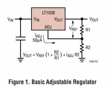
The LT1038 generates a 1.25V reference voltage across the chip's output and the adjustment pinouts (see Figure 1). By introducing a resistor, R1, between both of these pinouts, a constant current could be enabled to move by means of R1 and along R2 to create the actual output voltage. Usually this current acts like the particular minimum load current of 10 mA or 20 mA. Due to the fact IADJ is quite low and constant in comparison with the current through R1, it produces a tiny error potential, which can be ignored, in general.
Bypass Capacitors
In order to bypass and filter out resudual AC transients it is recommended to connect a 1µF tantalum or 25µF electrolytic across the input and ground terminals of the IC, especially when the input supply source is more than 5 inches away from the device.
Enhanced ripple rejection (80dB) could be achieved by incorporating a 10µF capacitor between the ADJ pinout and ground line. Using a larger 20µF capacitor might even help ripple rejection with lower output voltage because the capacitor reactance must be quite low than the voltage determining resistor, R2. In order to get a superior AC transient results and also to protect against unwanted oscillation caused by unfamiliar reactive load, a 1µF capacitor is likewise advised across the output supply lines of the IC. Owing of their low impedance at high frequencies, the most effective kind of capacitor that is encouraged are the solid tantalum types.
Protection Diodes
A protection diode between the adjustment terminal to the output is simply not necessary in a LT1038 circuit (see Figure 2). The in-built advanced circuitry ensures that the IC can work safely even when the adjustment pin is bypassed with a capacitor in order to enhance ripple rejection.
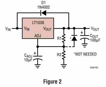
In case an incredibly big output capacitor is employed, say for example a 100 µF as indicated in Figure 2, the LT1308 regulator could possibly be destroyed or ruined when the input side terminals are inadvertently shorted to or shunted to ground, because of the output capacitor discharging into the output terminal of the regulator. To counteract this, a diode, D1 as demonstrated, is usually recommended to securely discharge the capacitor.
Load Regulation
Since the LT1038 is a three-terminal unit, it is not necessarily achievable to deliver genuine remote load detection. Load regulation is going to be restricted by the wire resistance linking the regulator with the load. The datasheet standards for load regulation is calculated towards the end of the bundle.

Negative side sensing could be a legitimate Kelvin relationship when the lower part of resistor R2 is connected back to the negative side of the load. Even though it might not be instantly apparent, most effective load regulation is attained if your upper end of the resistor divider, R1, is hooked up straight to the body, not to the load. This is highlighted in Figure 3. In case R1 had been attached to the load, the effective resistance across the regulator and the load would be:
Rp.(R2 + R1 / R1)Rp = Parasitic Line Resistance
Joined as indicated, Rp is not really multiplied by the divider ratio. Rp is approximately 0.004Ω for every foot applying 16 gauge wire. This means 4mV/ft at 1A load current, therefore it is crucial to maintain the lead between the regulator and the load as small as it can be, and work with thick wire or PC board tracks.
Leave a Reply