The variable voltage current power supply might look very small and compact physically, but it has the supply capacity of up to 3 A at 1.25-25 V output voltage.
However, when the power dissipation goes up to 30 W, the on-chip overload protection of the integrated voltage regulator IC1.
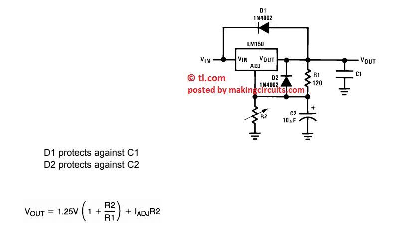
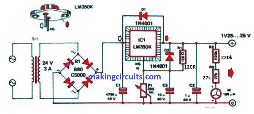
The basic schematic of this LM350 variable voltage power supply is shown below:

How the Circuit Works
The junction of the R1-P1 potential divider has the ADJ(ust) pin of the regulator connected to it. Output voltage Uo can be calculated using the formula
Uo = [ 1.25 (1 + P1/R1) ] V

As shown in the above detailed circuit diagram the unit of P1 and R1 is ohms. P1 lies between 1-2.5 kΩ, measured between the wiper and the junction with R1.
C1 here is a normal filter capacitor while C2 and C3 help improve regulation. D1 and D2 are protection diodes needed to ensure a higher positive potential at the output of IC1 than the input at switch-off.
R1 is so chosen that its value maintains a minimum load current of 3.5 A through IC1. IC1 must be mounted on a 1 K/W rated heat sink using sufficient heat-conducting paste.
At low output voltage requirements, a mains transformer with a lower secondary voltage should be used ( 9 V secondary voltage for Uo = 5 V ).
With a 24 V secondary and 1.25 V required output, the maximum output current should be 1 A from LM 350 variable power supply circuit.
Otherwise, the dissipation in the LM 350 will go over the maximum permissible limit.
This will cause the internal protection to turn the regulator off. On the other hand, the maximum load current comes to 2.5 A when the secondary is 9 V and the output is 1.25 V.
Leave a Reply